DIVISION ONE
Abbreviations & Definitions
101 Abbreviations
AC | Air Conditioning |
ASHRAE | American Society of Heating, Refrigerating and Air Conditioning Engineers |
ATTMA | Air Tightness Testing & Measurement Association |
BMS | Building Management System |
BSRIA | Building Services Research and Information Association |
BUA | Built Up Area |
CFC | Chlorofluorocarbons |
CIBSE | Chartered Institution of Building Services Engineers |
COP | Coefficient of Performance |
CWMP | Construction Waste Management Plan |
EER | Energy Efficiency Rating |
ESMA | Emirates Authority for Standardization and Metrology |
EV | Electric Vehicle |
GFA | Gross Floor Area |
GWP | Global Warming Potential |
HCFC | Hydrochlorofluorocarbons |
HFC | Hydrofluorocarbons |
HVAC | Heating, Ventilation and Air Conditioning |
IPLV | Integrated Part Load Value |
LED | Light Emitting Diode |
LPD | Lighting Power Density |
MEP | Mechanical, Electrical and Plumbing |
MERV | Minimum Efficiency Reporting Value |
ODP | Ozone Depletion Potential |
OWMP | Operational Waste Management Plan |
RAK | Ras Al Khaimah |
SHGC | Solar Heat Gain Coefficient |
SRI | Solar Reflective Index |
VOC | Volatile Organic Compound |
102 Definitions
Adaptive Species | A plant species, not originally part of the natural ecosystem, which has evolved to a point where the environmental conditions such as soil, climate and geology allow for healthy growth with no or minimal irrigation requirements. |
Air Leakage | The uncontrolled flow of air into a building through cracks or openings. |
Building Commissioning | A systematic quality assurance process to ensure the systems and assemblies are designed, installed and tested as per the design intent, contract document and the owner’s operational needs. |
Building Envelope | The exterior elements of a building which form a barrier between the internal and external spaces. For an air-conditioned building, the Building Envelope is defined as the elements of a building that separate conditioned spaces from the exterior. |
Building Management System (BMS) | A computer-based Control System installed in buildings that controls and monitors the building’s mechanical and electrical equipment, such as ventilation, lighting, power systems, fire systems and security systems. |
Building Occupant | Persons using the building. Full-time occupants use the building for at least eight hours most days. Part-time occupants use the building for less than eight hours most days. |
Building Owner | The person or establishment (or their representative) who owns the building and/or the land on which the building works (construction, refurbishing, demolition or removal of a building) are to be performed. |
Building Permit | The type of authorization that must be granted by the Competent Authority before the construction of buildings can legally occur. |
Building Services | All necessary services required to operate the building such as plumbing, mechanical, electrical and others. |
Chlorofluorocarbons (CFCs) | CFCs are odourless, colourless, non-flammable and non-toxic chemicals used for different applications, e.g. as coolants in refrigerators and air conditioners. CFCs cause stratospheric ozone depletion. |
Competent Authority | Any organization that has the jurisdiction and authority to implement the Green Building Regulations. |
Completion Certificate | Certificate issued by the Competent Authority certifying that the project has been completed in accordance with the legal requirements. |
Comprehensive Green Building Regulations | The Comprehensive Green Building Regulations, compared to the Fundamental Green Building Regulations, are more elaborate regulations intended for application to larger and more complex buildings. |
Condensation | The process through which a gas or vapour changes to liquid form. May also mean the water which is produced in this process. |
Construction Waste | Waste generated from construction, renovation, and demolition or deconstruction of structures. Land Clearing Debris including soil, vegetation and rocks are typically not considered Construction Waste. |
Control Systems | Controls that allow users to change and/or adjust the level of lighting and air conditioning in a space. |
Cooling Load | The rate at which heat energy must be heat energy that would need to be removed from a space to maintain the temperature in an acceptable range. |
Drip Irrigation | A high-efficiency irrigation method where water is delivered at low pressure through buried pipes and sub-pipes, which in turn distribute water to the soil from a network of perforated tubes or emitters. |
Electric Vehicle (EV) Charging Station | A general term that refers to an operational site used for charge electric vehicle batteries. |
Emissivity | The material’s effectiveness in emitting energy as thermal radiation. It is expressed as a parameter with values between 0 and 1. |
Fundamental Green Building Regulations | The Fundamental Green Building Regulations are simplified regulations for industrial buildings, villas and small scale residential, office and retail buildings. |
Glazed Elements | All areas in the building envelope that let in light, including windows, plastic panels, skylights and glass block walls. |
Global Warming Potential (GWP) | Expresses contribution of greenhouse gases released to the atmosphere in the global warming phenomenon. |
Government Funded Private Villas | Villas developed by government entities for UAE nationals. |
Green Roofs | A roof that is either partially or completely covered in plants. A Green Roof consists of vegetation and soil, or a growing medium, planted over a waterproof membrane. Additional layers, such as a root barrier and drainage and irrigation system may also be part of a Green Roof. |
Greywater | Waste water without faecal contamination that is generated in residential, public or commercial buildings. Sources of Greywater include sinks, showers, bathtubs, clothes washing machine, dish washing machine and other kitchen appliances. |
Halons | Substances used in fire suppression systems and fire extinguishers. These substances deplete the stratospheric ozone layer. |
Hardscape | The area of a project site, excluding buildings, that has been built out of hard materials such as concrete. Hardscape includes roads, surface car parking, patios, courtyards and walkways. |
Hazardous Waste | Any waste material that can cause substantial harm to humans, properties or to the environment due to its inherent hazardous characteristics. |
Heating, Ventilation, And Air Conditioning (HVAC) System | The equipment, distribution systems and terminals that provide either individually or collectively, the processes of heating, ventilation, or air conditioning to a building or a portion of a building. |
Heritage Building | A building having historical architectural elements, situated inside a Ras Al Khaimah historical area. No demolition or variation works shall be carried out on a Heritage Building except after obtaining approval from the Competent Authority. |
Hydrochlorofluorocarbons (HCFC) | Refrigerants used in building equipment that cause the stratospheric ozone layer depletion. |
Hydrofluorocarbons (HFCs) | Refrigerants that do not deplete the stratospheric ozone layer. However, some HFCs have a high Global Warming Potential. |
Implementation Date | The effective date upon which the GBR enters into force. |
Individual Private Villa | Villas that are developed by UAE nationals for non-commercial use. |
Industrial Building | Any building directly used in manufacturing, processing, technically productive enterprises or storage. This includes workshops, factories and warehouses. |
Investment Villas | Villas developed for commercial use, e.g. villas that will be rented or sold. |
Land Clearing Debris | Solid waste generated solely from land-clearing activities, including brush, stumps, soil material and rocks. |
Landscape | The planting of trees, ground cover, shrubbery and other plant material (Softscape), as well as the provision of man-made, non-vegetated features (Hardscape) that serve an aesthetic or functional purpose. |
Legionella | Bacteria that are the causative agent of Legionnaires' disease and its lesser form, Pontiac fever. The bacteria grow in water between 20 and 45 degrees Celsius and can be spread by water droplets. |
Light-Emitting Diode (LED) | A semiconductor device that emits incoherent narrow-spectrum light. |
Lighting Power Density (LPD) | Lighting Power Density (LPD) represents the maximum lighting power per unit area and is typically expressed as wattage per square meters. |
Minimum Efficiency Reporting Value (MERV) | An expression of the filtering efficiency of an air filter that has been evaluated using the ASHRAE Standard 52.2 Test Procedure. An air filter’s performance is determined by comparing airborne particle counts upstream and downstream of the air filter (or other air cleaning device) under test conditions. A higher MERV rating equates to higher air filtration efficiency. |
Native Species | A plant species that occurs naturally within a region or ecosystem, with no human intervention. |
Net Roof Area | The remaining roof area after excluding the area of any skylights, helipads and solar water heating equipment from the gross roof area of the building. The area of any sloping roofs, roof decks, terraces, swimming pools, HVAC equipment, vents and areas for maintenance access that are part of the roof must be included in the Net Roof Area. |
Non-Native Species | A plant species, not native to a particular region, which has been introduced, accidentally or deliberately, by human activity and has not adapted to the environmental conditions of that particular region. |
Non-Potable Water | Water that is not suitable for human consumption such as Greywater, recovered condensate water or Treated Sewage Effluent. |
Occupancy Sensor | A device that detects the presence or absence of people within an area and causes lighting, equipment, or appliances to be regulated accordingly. |
Occupant Lighting Controls | A means of controlling the level of lighting which is easily accessible to a building occupant. Includes on/off switches. |
Opaque | All areas of a building envelope which do not transmit light. Fenestration and building service openings, such as vents and grilles, are not opaque. |
Ozone Depletion Potential (ODP) | Expresses contribution to the deterioration of the stratospheric ozone layer. |
Photovoltaic (PV) | A power system designed to supply usable solar power by means of photovoltaics. |
Potable Water | Water that is suitable for human consumption. |
Pressure Difference | The difference in pressure between two points of a system, or two different spaces of a building. |
Prevalent Usage Type | The usage type representing the highest share of Gross Floor Area (GFA) of a building compared to all other usage types assigned to other areas of the building. |
Recycling | The processing of used materials into new products in order to prevent the waste of potentially useful materials and reduce the need for waste disposal. |
Reflectivity | A measure of the ability of a material to reflect solar energy from its surface back into the atmosphere. It is expressed as a parameter with values between 0 and 1. |
Refrigerants | The working fluids of refrigeration cycles, which absorb heat at low temperatures and release heat at higher temperatures. |
Regularly Occupied Areas | An area where one or more individuals regularly spend time, seated or standing as they perform various activities inside a building. |
Relative Humidity | The ratio of the amount of water vapour in the air at a specific temperature to the maximum amount of water vapour the air can hold at the same temperature, expressed as a percentage. |
Reuse | Any activity that extends the life of an item, typically consisting of returning the item to active use in the same or related capacity. |
Safety Factor | An allowance to cover any heating or cooling load greater than the design conditions. |
Softscape | The planting of trees, ground cover, shrubbery and other plant material. Agricultural farming is not considered softscaping. |
Solar Heat Gain Coefficient (SHGC) | Indicates the effectiveness of the glazing in rejecting solar heat gain. It ranges from 0 to 1 and the lower the SHGC the more heat is being rejected and thus less heat is being transmitted into the building. The SHGC factors in both the glass and the frame material. Since the area of a frame has a relatively low SHGC, the overall window SHGC is lower than the centre-of-glass value. |
Solar Reflectance Index (SRI) | An index that combines Reflectivity and Emissivity, measuring a material’s ability to reject solar heat. Materials with higher SRI absorb less heat and can reduce the heat islands effect. |
Solar Zone | The area on the roof of the building or on an adjacent accessory structure (e.g. covered parking, service block, gazebo) that is reserved for on-site PV readiness. |
Special Building | The status of a Special Building can be obtained from the Competent Authority for iconic buildings with a unique architecture or usage that are unable to comply with certain requirements of the Green Building Regulations. |
Subsoil Irrigation | Uniform application of small quantities of water at frequent intervals below the soil surface from discrete emission points or line sources. |
Temporary Building | Any building that will be removed within two years after its construction. |
Thermal Bridge | A direct connection between the inside and outside of the building through elements that have a higher conductivity than the surrounding materials or through the junctions between various envelope elements. |
Thermal Insulation | Materials, or methods and processes used to reduce heat transfer. |
Thermal Transmittance | Also known as U-Value, is the rate of transfer of heat (in watts) through one square meter of a structure divided by the difference in temperature across the structure. It is expressed in watts per square meter per degree kelvin, or W/m²K. Well-insulated parts of a building have a low thermal transmittance whereas poorly insulated parts of a building have a high thermal transmittance. |
Thermally Broken Frame | A frame consisting of an insulating separator material between the inner and outer frames to prevent heat transfer through the frame and condensation. |
Treated Sewage Effluent (TSE) | The product of the process of removing physical, chemical and biological contaminants from wastewater. The process produces treated effluent suitable for reuse or discharge into the environment and solid waste (or sludge). |
Urban Heat Island Effect | This occurs when warmer temperatures are experienced in urban and/or developed areas compared to adjacent undeveloped areas due to solar energy retention on constructed surfaces. Examples of surfaces that contribute to the Urban Heat Island Effect are paved streets, sidewalks, parking lots and buildings. |
Volatile Organic Compounds (VOCs) | Molecules containing carbon and varying proportions of other elements such as hydrogen, oxygen, fluorine, and chlorine. They are the “precursors” that react in sunlight and heat to form ground-level ozone. |
DIVISION TWO Preambles
201 Chapter 1 – General
The regulations outlined in this document represent the Ras Al Khaimah Green Building Regulations and shall be known and cited as Barjeel. Within this document they are also referred to as “the GBR”.
201.01 Purpose
The GBR intend to support the United Arab Emirates’ vision of creating more sustainable buildings, communities and cities to fulfil the social, economic, cultural and environmental requirements for the present and future generations.
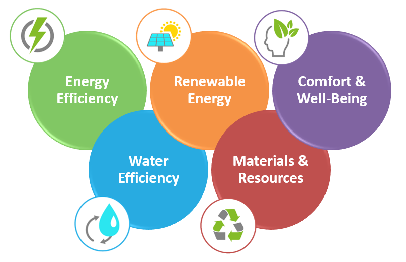
The aim of the GBR is to transform the construction industry in Ras Al Khaimah to achieve the following goals:
Conservation of energy resources |
Conservation of water resources |
Implementation of renewable energy |
Promotion of sustainable building materials and reduction of waste |
Enhancement of occupants’ comfort & well-being |
By conserving energy and water resources, the GBR will also result in lower operational and life-cycle costs of buildings.
201.02 Jurisdiction and Competent Authority
The GBR are applicable in the entire Emirate of Ras Al Khaimah.
Ras Al Khaimah Municipality (RAK Municipality) is the Competent Authority for the application of the GBR within the jurisdiction of RAK Municipality. The economic and free zone authorities, such as RAKEZ, Maritime City, RAK Port and RAK Airport, are the Competent Authorities for the application of the GBR within their jurisdiction.
201.03 Compatibility with Existing Regulations
The GBR complement the RAK Municipality General Building Regulations of the Emirate of Ras Al Khaimah for projects within the jurisdiction of RAK Municipality.
The provisions within the GBR shall supersede the provisions of any pre-existing regulations in case of conflict, without any effect on the continuing validity of the remaining non-conflicting provisions of the pre-existing regulations.
When the requirements of the GBR differ from the requirements of Ras Al Khaimah Civil Defence Department or differ from the requirements of local and/or federal laws, the requirements of Ras Al Khaimah Civil Defence Department as well as the requirements of the local and/or of the federal laws will prevail.
The regulations are issued in two languages, Arabic and English. The Arabic version shall prevail in any case of conflict.
201.04 Building Typology
For the purpose of the GBR, requirements are defined for the following building typologies:
Residential Buildings
Villas:
Individual Private Villa
Government Funded Private Villa
Investment Villa
Annex (for Villa)
Buildings:
Multi-Story Residential Building
Staff Accommodation
Labour Accommodation
Student Accommodation
Public Buildings
Government Building
Educational Facility
Healthcare Facility
Mosque & Worship
Building
Exhibition & Festival
Center, Sport Facility
Other Public Building (Bank, Post Office, Cinema, Theatre, Museum)
Office Building
Mall & Shopping Center
Retail & Showroom
Laboratory (Private)
Hotel
Motel
Resort
Hotel Apartment
Factory
Warehouse
Workshop
Hospitality Buildings
Industrial Buildings
Commercial Buildings
201.05 Scope of Application
With regards to the building typologies identified above, the GBR apply to:
New buildings, on empty plots and on occupied plots, whose Building Permit application has been submitted after the Implementation Date of the GBR
Extensions and/or refurbishments of buildings permitted under the GBR
The following building types are exempt from the regulations:
Temporary Buildings
Heritage Buildings
New buildings, on empty plots and on occupied plots, whose Building Permit application has been completely submitted before the Implementation Date of the GBR.
Extensions and/or refurbishments of buildings permitted prior to the GBR
For mixed use buildings, when a building comprises more than one building usage type, the whole building shall comply with the requirements of the Prevalent Usage Type which is subject to the approval from the Competent Authority. In case the Prevalent Usage Type is not clear, the applicable building usage type for the GBR shall be defined in coordination with the Competent Authority.
For projects comprising several buildings, each building of the project must comply with the relevant regulations for that particular building type.
201.06 Regulatory Approach and Compliance Methods
The objective of the GBR is to establish green building requirements that are applied to new buildings, extensions and refurbishments in the entire Emirate of Ras Al Khaimah. The GBR are categorised into two groups:
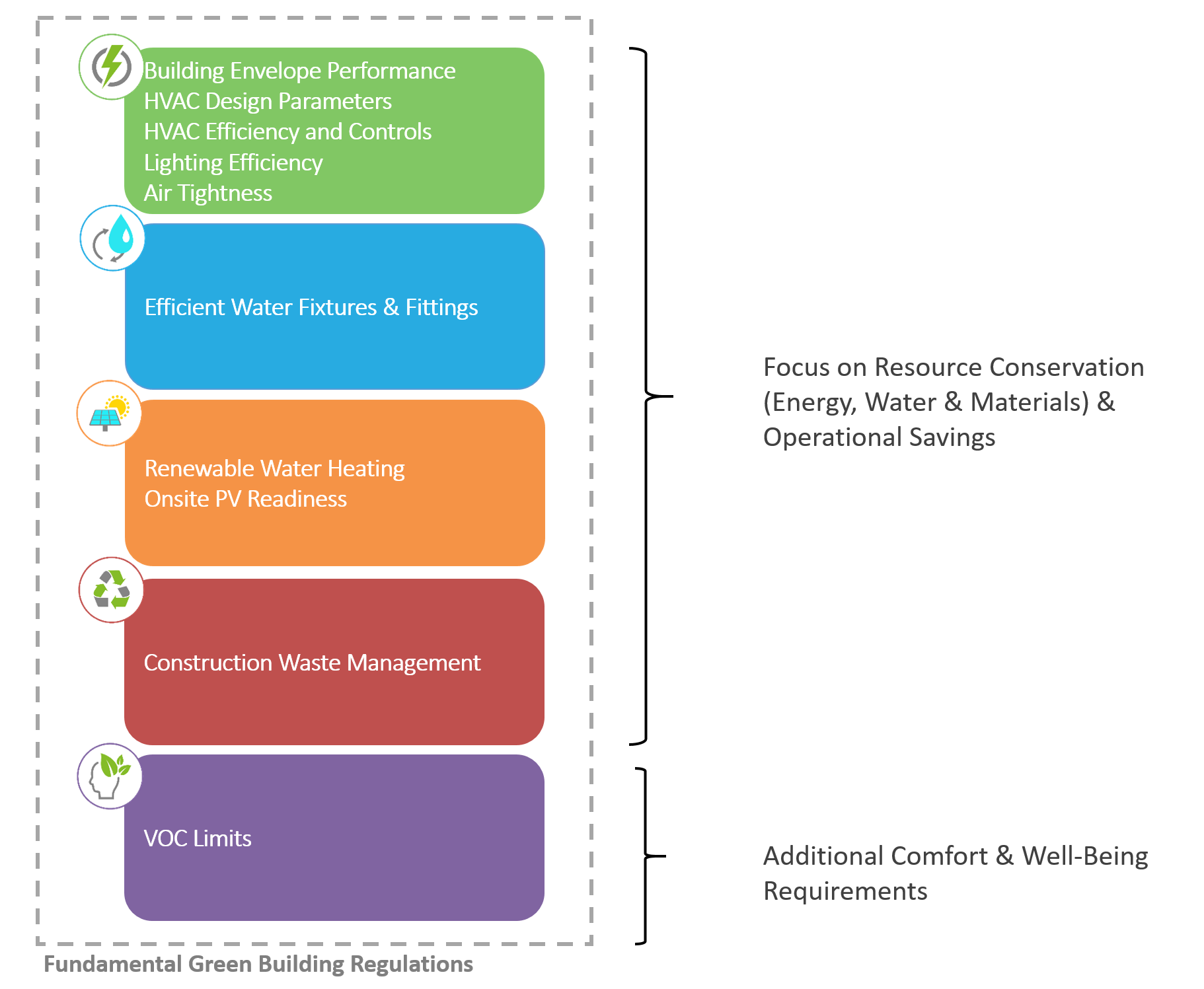
Fundamental Green Building Regulations:
The Fundamental Green Building Regulations are simplified regulations in the form of prescriptive compliance requirements with some performance-based compliance requirements. These regulations mainly focus on resource conservation and are intended for relatively small and/or simple buildings, for which compliance with the full requirements may be complex or costly.
The following building types must comply with the requirements within the Fundamental Green Building Regulations:
Table 1 Fundamental Green Building Regulations – Building Typologies
Residential | Commercial | Industrial | |
Individual Private Villa incl. Annex | Office Building (max. 1,000 m2 BUA) | Workshop | |
Government Funded Private Villa incl. Annex | Retail & Showroom (max. 1,000 m2 BUA) | Warehouse | |
Investment Villa incl. Annex | Public | Factory | |
Residential Building (max. 1,000 m2 BUA) | Mosque & Worship Building (max. 1,000 m2 BUA) | ||
Staff, Labour and Student Accommodation (max. 1,000 m2 BUA) | Other Building (non-residential or commercial (max. 1,000 m2 BUA) | ||
The BUA limit is calculated separately for each building.
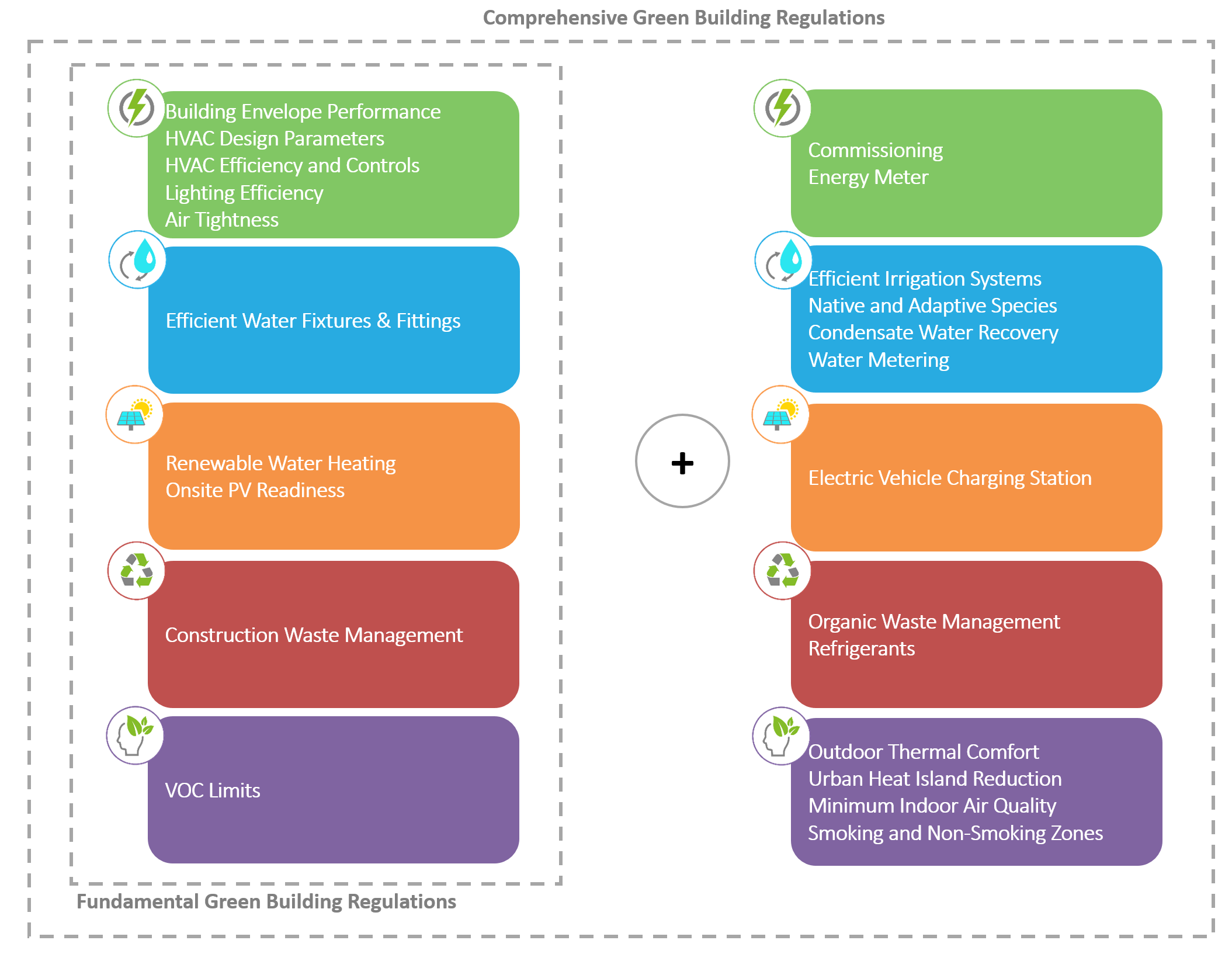
Comprehensive Green Building Regulations:
The Comprehensive Green Building Regulations are more elaborate regulations focusing on performance-based compliance requirements. Apart from energy and water efficiency, they address a broader range of topics related to materials & resources and comfort & well-being of the building occupants. These regulations are intended for application to larger and more complex buildings.
The following building types must comply with the Comprehensive Green Building Regulations:
Table 2 Comprehensive Green Building Regulations – Building Typologies
Residential | Commercial | Public |
Residential Building (> 1,000 m2 BUA) | Office Building (> 1,000 m2 BUA) | Mosque & Worship Building (> 1,000 m2 BUA) |
Staff, Labour and Student Accommodation (> 1,000 m2 BUA) | Retail & Showroom (> 1,000 m2 BUA) | Government Building |
Hospitality | Mall & Shopping Centre | Educational Facility |
Hotel, Motel | Laboratory | Healthcare Facility |
Hotel Apartment | Exhibition & Festival Centre, Sports Facility | |
Resort | Other Public Building |
The BUA limit is calculated separately for each building.
Special Buildings:
Buildings with exceptional architectural characteristics or special usage that are unable to comply with certain requirements may contact the Competent Authority to apply for the status as a Special Building. Special Buildings may follow an alternative approach for these requirements, which will be defined in liaison with the Competent Authority and will be meant to find compensatory measures for those requirements that cannot be fulfilled.
As an example, the following buildings might be classified as Special Buildings:
Adventure and water parks
Buildings with a unique and iconic architecture
Shopping malls with ski slopes
Hotels with helipads
Specialty laboratories
Skydiving buildings
Classification of a building as a Special Building for the purpose of the GBR is subject to the exclusive decision of the Competent Authority.
201.07 Structure of the Regulations
Both the Fundamental and the Comprehensive Green Building Regulations presented within this document are divided into five categories as illustrated in Figure 1.
The categories include several articles, each article describing one regulatory item within the GBR.
The description of every regulatory item is structured as follows:
Intent: This section provides a brief of the intention behind implementing the regulatory item.
Applicable Building Types: This section lists the types of buildings which need to comply with the regulatory item.
Requirements: This section describes the minimum requirements which need to be fulfilled in order to achieve compliance with the regulatory item.
Guideline: This section provides guidance and indicates possible methods to achieve compliance with the requirements. These guidelines are for information purposes only. They do not represent any form of restriction or requirement for the building design and construction; adherence to the guidelines does not guarantee compliance with the regulations.
Submission Stage and Evidence: This section indicates the applicable submission stages and details the documentary evidence that is required to prove compliance with the regulatory item. The specified evidence shall be submitted to the Competent Authority over the course of the submission process described in Chapter 2 of this document.
202 Chapter 2 – Submission Process
Compliance with the GBR is proven through a design stage and a construction stage submission. The applicable submission stages and the required submission evidence are specified for each regulatory item.
The submission process is described in the paragraphs 202.01 and 202.02. The Competent Authority may require a different process to be applied within their jurisdiction.
202.01 Design Stage Submission
The GBR design stage evidence is to be submitted, along with the other documents and drawings required for the Building Permit application, as per the requirements of the Competent Authority.
The relevant sections demonstrating compliance with the GBR are to be clearly highlighted in documents, calculations and drawings.
The applicant has to ensure that the project fulfils all applicable requirements of the GBR without any conflict and/or contradiction with other documents and drawings required as part of the Building Permit application.
The Building Permit issuance depends on the project’s compliance with the GBR along with other requirements as defined by the Competent Authority.
202.02 Construction Stage Submission
The GBR construction stage evidence shall be recorded on a monthly basis. The recorded evidence must be submitted to the Competent Authority upon request.
The Competent Authority may conduct site visits at any time to review the compliance with the GBR requirements.
The GBR construction stage evidence is to be submitted, along with the other documents and drawings required for the Completion Certification application, as per the requirements of the Competent Authority.
The relevant sections demonstrating compliance with the GBR are to be clearly highlighted in the material datasheet and technical product information documents.
The applicant has to ensure that the project fulfils all applicable requirements without any conflict and/or contradiction with the other disciplines’ documents and drawings.
The Completion Certificate issuance depends on the project’s compliance with the GBR along with other requirements as defined by the Competent Authority.
Fundamental Green Building Regulations
DIVISION THREE: Fundamental Green Building Regulations
The Fundamental Green Building Regulations are applicable to the following building types:
Table 3 Fundamental Green Building Regulations – Applicable Building Types
Residential | Commercial | Industrial | |
Individual Private Villa incl. Annex | Office Building (max. 1,000 m2 BUA) | Workshop | |
Government Funded Private Villa incl. Annex | Retail & Showroom (max. 1,000 m2 BUA) | Warehouse | |
Investment Villa incl. Annex | Public | Factory | |
Residential Building (max. 1,000 m2 BUA) | Mosque & Worship Building (max. 1,000 m2 BUA) | ||
Staff, Labour and Student Accommodation (max. 1,000 m2 BUA) | Other Building (non-residential or commercial (max. 1,000 m2 BUA) | ||
Figure 2 lists the regulatory items of the Fundamental Green Building Regulations.
Figure 2 Fundamental Green Building Regulations – Regulatory Items
301 Chapter 1 – Energy Efficiency
301.01 Building Envelope Performance
Intent:
To reduce the heat gain through the building’s façades and roof and consequently minimise the cooling load which represents a significant component of the total building energy consumption.
Applicable Building Types:
Residential | Commercial | Industrial | |||
Individual Private Villa incl. Annex | ☑ | Office Building (max. 1,000 m2 BUA) | ☑ | Workshop | 🗵 |
Government Funded Private Villa incl. Annex | ☑ | Retail & Showroom (max. 1,000 m2 BUA) | ☑ | Warehouse | 🗵 |
Investment Villa incl. Annex | ☑ | Public | Factory | 🗵 | |
Residential Building (max. 1,000 m2 BUA) | ☑ | Mosque & Worship Building (max. 1,000 m2 BUA) | ☑ | ||
Staff, Labour and Student Accommodation (max. 1,000 m2 BUA) | ☑ | Other Building (non-residential or commercial (max. 1,000 m2 BUA) | ☑ | ||
Requirements:
The building envelope performance requirements are formulated separately for opaque elements (such as external walls and roofs) and glazed elements (such as windows, glazed walls and skylights).
Opaque glazed elements (with back insulated panels) are considered as opaque elements, and therefore must meet the required u-value of the walls.
Requirements for Opaque Elements:
The average u-value of the external walls and roofs (that are exposed to ambient conditions) must not exceed the following thresholds:
Average external wall u-value ≤ 0.48 W/m²K
Average roof u-value ≤ 0.30 W/m²K
Individual Private Villas are exempt from the above specified external wall u-value if 200 mm thermal blocks with u-value of maximum 0.5 W/m²K are used.
All applicable building types, except for Individual Private Villas, must insulate the external structural columns and beams to avoid heat bridges.
Requirements for Glazed Elements:
The optimum choice of windows is important as glazing gains and loses heat quickly and often makes up a large proportion of the building envelope.
For glazed portions of external walls and roofs, the average u-value and Solar Heat Gain Coefficient (SHGC) should not exceed the following values:
Window centre pane u-value ≤ 1.8 W/m²K
Skylight centre pane u-value ≤ 1.8 W/m²K
Window and skylight SHGC ≤ 0.3
Exception(s):
Buildings that are not air-conditioned do not have to comply with this article.
Guideline:
Opaque Elements:
The following options are likely to achieve the required roof and wall u-values:
External walls:
Individual Private Villas:
200 mm thermal blocks with a maximum u-value of 0.5 W/m²K and a 25 mm internal & external plaster.
All other applicable building types:
Option 1: 200 – 250 mm thermal blocks with a 25 mm internal & external plaster. Additionally, the structural columns and beams should be insulated to avoid heat bridges and to achieve the average external wall u-value of 0.48 W/m²K.
Option 2: 50 – 100 mm insulation layer, bonding plaster and reinforcement mesh. The insulation layer should be applied on the hollow concrete blocks, the structural columns and beams and should be continuous and cover all gaps between the building envelope elements.
Roof:
Combo roofing system with 30 – 50 mm insulation layer
Glazing Elements:
The following options are likely to achieve the required glazing properties:
Double glazing (6 mm pane + 12 mm air gap + 6 mm pane) with a low solar coating on the interior of the outside pane
Submission Stage and Evidence:
Design Stage:
Barjeel Tool - U-Value Calculator (not required for Individual Private Villas)
Wall and roof cross sections showing the composition (thickness and material type) of the different wall and roof systems
Extract of the tender specifications, material schedule or bill of quantities highlighting the required u-values and SHGC
Construction Stage:
Technical product information or material datasheet for the insulation materials and/or thermal blocks
Date-stamped photos showing the installation of the thermal blocks and/or insulation layers
301.02 HVAC Design Parameters
Intent:
To prevent oversizing of the air conditioning equipment by considering local weather conditions, required indoor conditions and the building envelope performance.
Applicable Building Types:
Residential | Commercial | Industrial | |||
Individual Private Villa incl. Annex | 🗵 | Office Building (max. 1,000 m2 BUA) | ☑ | Workshop | ☑ |
Government Funded Private Villa incl. Annex | ☑ | Retail & Showroom (max. 1,000 m2 BUA) | ☑ | Warehouse | ☑ |
Investment Villa incl. Annex | ☑ | Public | Factory | ☑ | |
Residential Building (max. 1,000 m2 BUA) | ☑ | Mosque & Worship Building (max. 1,000 m2 BUA) | ☑ | ||
Staff, Labour and Student Accommodation (max. 1,000 m2 BUA) | ☑ | Other Building (non-residential or commercial (max. 1,000 m2 BUA) | ☑ | ||
Requirements:
The cooling load must be calculated in accordance with the following design parameters:
Building Envelope Parameters
The heat transfer coefficients for walls, roofs and glazing must be the actual design coefficients and must comply with the article 301.01 ‘Building Envelope Performance’.
Outdoor Condition of the Building
Dry bulb temperature: 46°C
Wet bulb temperature: 29°C
Ras Al Khaimah City location latitude (North Latitude) 25.5°N
Indoor Condition of the Building
For all regularly occupied rooms, excluding spaces dedicated to manufacturing, production and storage:
Dry bulb temperature: 24°C +/- 1°C
Relative humidity: 50% +/- 10%
The diversity coefficients set out in the ASHRAE Fundamentals 2013 shall be used.
Safety Factors
The safety factors applied must be no greater than the following:
Sensible Heat: 10%
Latent Heat: 5%
Exception(s):
Buildings that are not air-conditioned do not have to comply with this article.
Guideline:
The actual design heat transfer coefficients and the specified outdoor and indoor conditions should be used in the cooling load calculations.
It is recommended to use a static or dynamic software for the cooling load calculations. These software tools can generate various reports which can be submitted to demonstrate compliance with this article.
Submission Stage and Evidence:
Design Stage:
Simple AC drawings showing the AC type and capacity
Cooling load calculations or simulation reports highlighting the applied design parameters
301.03 HVAC Efficiency & Controls
Intent:
To promote efficient Heating, Ventilation and Air Conditioning (HVAC) systems and to ensure adequate controls are available to the building occupants to adjust the set-point temperature and ventilation settings.
Applicable Building Types:
Residential | Commercial | Industrial | |||||||||
Individual Private Villa incl. Annex | ☑ | Office Building (max. 1,000 m2 BUA) | ☑ | Workshop | ☑ | ||||||
Government Funded Private Villa incl. Annex | ☑ | Retail & Showroom (max. 1,000 m2 BUA) | ☑ | Warehouse | ☑ | ||||||
Investment Villa incl. Annex | ☑ | Public | Factory | ☑ | |||||||
Residential Building (max. 1,000 m2 BUA) | ☑ | Mosque & Worship Building (max. 1,000 m2 BUA) | ☑ | ||||||||
Staff, Labour and Student Accommodation (max. 1,000 m2 BUA) | ☑ | Other Building (non-residential or commercial (max. 1,000 m2 BUA) | ☑ | ||||||||
Requirements:
HVAC Efficiency
All HVAC equipment and systems must comply with the minimum full load energy efficiency requirements (EER/COP) listed in Table 4, Table 5 and Table 6. Chilling packages must additionally comply with the minimum part load efficiency requirements (IPLV) specified in Table 7.
Table 4 Fundamental Green Building Regulations – Electrically Operated Unitary ACs
Equipment Type | Rated Capacity (kW at T3) | Minimum Efficiency Full Load | Rating Conditions | |
Energy Efficiency Rating (EER, Btu/h/W at T3) | Coefficient of Performance (COP at T3) | |||
Window AC | All | 7.51 | 2.20 | Tested as per ESMA standard no. UAE.S ISO 5151:2017 |
Non-ducted AC | All | 8.31 | 2.44 | |
Ducted split & packaged AC | RC < 40 | 8.80 | 2.58 | Tested as per ISO 13253 |
40 ≤ RC < 70 | 8.59 | 2.52 | ||
70 ≤ RC < 223 | 8.27 | 2.42 | ||
223 ≤ RC | 7.95 | 2.33 | ||
Table 5 Fundamental Green Building Regulations – Multi-Split and VRF
Equipment Type | Rated Capacity (kW at T3) | Cooling Seasonal Performance Factor (CSPF Btu/h/W at T3) | Integrated Part Load Value (IPLV at T3) | Rating Conditions |
Multi Split | RC <40 | NA | 4.59 | Tested as per ESMA standard no. UAE.S ISO 15042 |
40 ≤ RC < 220 | NA | 4.45 | ||
220 ≤ RC | NA | 4.35 | ||
VRF | RC <40 | 14.84 | NA | Tested as per ESMA UAE.S ISO 16358-2013/Amd.1:2019 |
40 ≤ RC < 220 | 13.78 | NA | ||
220 ≤ RC | 13.25 | NA |
Table 6 Fundamental Green Building Regulations – Heat Pumps
Rated Capacity (kW at T3) | Minimum Efficiency Full Load | Rating Conditions | ||
Energy Efficiency Rating (EER, Btu/h/W at T3) | Coefficient of Performance (COP at T3) | |||
Water source heat pump unit | All Capacities, entering fluid temperature of 30°C | 8.35 | 2.45 | Tested as per ESMA standard no. UAE.S ISO 13256-1:1998 & UAE.S ISO 13256-2:1998 |
Ground water source heat pump unit | All Capacities, entering fluid temperature of 25°C | 9.2 | 2.7 | |
Table 7 Fundamental Green Building Regulations – Chilling Packages
Equipment Type | Rated Capacity (kW at T1) | Minimum Efficiency Full Load | Integrated Part Load Value (IPLV at T1) | Rating Conditions | |
Energy Efficiency Rating (EER, Btu/h/W at T1) | Coefficient of Performance (COP at T1) | ||||
Air cooled package chiller without condenser | All | 11.21 | 3.29 | 4.05 | Tested as per UAE.S AHRI 550/590 |
Air cooled package chiller with condenser | RC < 528 | 10.13 | 2.97 | 4.05 | |
528 ≤RC | 10.13 | 2.97 | 4.14 | ||
Water cooled chiller positive displacement (reciprocating) | All | 15.19 | 4.45 | 5.63 | |
Water cooled chiller positive displacement (rotary and scroll) | RC < 264 | 16.01 | 4.69 | 5.87 | |
264 ≤RC<528 | 17.03 | 4.99 | 6.29 | ||
528 ≤RC<1,055 | 18.19 | 5.33 | 6.52 | ||
1,055≤RC<2,110 | 19.69 | 5.77 | 6.77 | ||
2,110 ≤ RC | 21.26 | 6.23 | 7.04 | ||
Water cooled chiller (centrifugal) | RC < 528 | 21.71 | 6.36 | 6.77 | |
528 ≤ RC | 23.51 | 6.89 | 7.04 | ||
Air cooled absorption, single effect | All | 2.05 | 0.60 | NA | Tested as per AHRI 560 |
Water cooled absorption, single effect | All | 2.39 | 0.70 | NA | |
Absorption double effect, indirect fired | All | 3.41 | 1.00 | 1.05 | |
Absorption double effect, direct fired | All | 3.41 | 1.00 | 1.00 | |
HVAC Controls:
The HVAC control system of the building shall be subdivided into independent control areas, corresponding to the various regularly occupied rooms or areas of the building.
The set-point temperature and ventilation of each control area must be independently controllable, regardless of the set-point temperature and ventilation of other control areas in the building. A thermostat must be provided in each control area to allow occupants to adjust the set-point temperature and ventilation of the area.
The HVAC control system must be capable of shutting down and starting up the HVAC equipment for the specific control area whenever required by the occupants of the same control area.
In case of a central building HVAC system, the HVAC control system must shut down the central cooling equipment when the set-point temperature of all control areas has been reached, or when the thermostat for all control areas has been switched off.
Guideline:
HVAC Efficiency
The following options are likely to achieve the required HVAC efficiency requirements:
For window and non-ducted split AC units, use equipment that meets at least the 2-star rating standards of the Emirates Authority for Standardization and Metrology (ESMA) UAE.S 5010-1:2019.
For ducted split and packaged AC units, use equipment which is at least 6% more efficient than the minimum efficiency standard of the ESMA UAE.S 5010-5: 2019.
For multi-split and VRF units, use equipment which is at least 6% more efficient than the minimum efficiency standard of the ESMA UAE.S 5010-5: 2019.
For chilling packages use equipment that meets at least the efficiencies outlined in Table 7.
HVAC Controls
Provide one set-point control for each regularly occupied room, near the entrance of the room.
Submission Stage and Evidence:
Design Stage:
Extract of the tender specifications, material schedule or bill of quantities showing the specified HVAC systems, rated capacities and associated efficiencies (COP/EER and IPLV if applicable)
HVAC control schematics
Construction Stage:
Technical product information or datasheet of the HVAC equipment which include the following information:
Rated Capacity
COP/EER and IPLV (IPLV only for chilling packages)
Testing Method
301.04 Lighting Efficiency
Intent:
To reduce the electricity consumption by mandating energy efficient lighting fixtures and lighting controls.
Applicable Building Types:
Residential | Commercial | Industrial | |||
Individual Private Villa incl. Annex | 🗵 | Office Building (max. 1,000 m2 BUA) | ☑ | Workshop | ☑ |
Government Funded Private Villa incl. Annex | ☑ | Retail & Showroom (max. 1,000 m2 BUA) | ☑ | Warehouse | ☑ |
Investment Villa incl. Annex | ☑ | Public | Factory | ☑ | |
Residential Building (max. 1,000 m2 BUA) | ☑ | Mosque & Worship Building (max. 1,000 m2 BUA) | ☑ | ||
Staff, Labour and Student Accommodation (max. 1,000 m2 BUA) | ☑ | Other Building (non-residential or commercial (max. 1,000 m2 BUA) | ☑ | ||
Requirements:
Lighting Efficiency
All internal and external light fittings of the building must be Light Emitting Diodes (LEDs) or meet, at a minimum, the ESMA 3-star requirements.
Lighting Controls
At least one light switch or dimmer must be provided near the entrance of each room.
Exception(s):
The following lighting types are exempt from the lighting efficiency requirements:
Lighting for specialised plant, machinery and equipment
Coloured lighting
Lighting for plant growth
Lighting for visually impaired persons with special lighting needs
Guideline:
Light Emitting Diodes (LEDs) may be preferred over incandescent lamps as LEDs are highly energy efficient and have a long life expectancy.
It is recommended to provide dimmers or multiple light switches to allow occupants to adjust the lighting to suit their individual tasks and preferences.
Submission Stage and Evidence:
Design Stage:
Luminaire schedule indicating the lighting fixture type, ESMA star rating (for incandescent lamps) and wattage
Lighting control schematics
301.05 Air Tightness
Intent:
To optimise the air tightness of the buildings and minimise air leakage.
Air leakage control is essential to optimise the energy performance of the building. If the building envelope is not sufficiently airtight, cold air leaks out and hot air enters through gaps and cracks, resulting in higher energy consumption. Air leakage may also cause condensation issues, accelerating mould growth.
Applicable Building Types:
Residential | Commercial | Industrial | |||
Individual Private Villa incl. Annex | 🗵 | Office Building (max. 1,000 m2 BUA) | ☑ | Workshop | 🗵 |
Government Funded Private Villa incl. Annex | ☑ | Retail & Showroom (max. 1,000 m2 BUA) | 🗵 | Warehouse | 🗵 |
Investment Villa incl. Annex | ☑ | Public | Factory | 🗵 | |
Residential Building (max. 1,000 m2 BUA) | ☑ | Mosque & Worship Building (max. 1,000 m2 BUA) | ☑ | ||
Staff, Labour and Student Accommodation (max. 1,000 m2 BUA) | ☑ | Other Building (non-residential or commercial (max. 1,000 m2 BUA) | ☑ | ||
Requirements:
An air leakage site inspection shall be performed at approximately 60% completion of the building envelope. The air leakage site inspection shall be conducted by the supervision consultant engineer or the contracting company engineer approved by the supervision consultant engineer. The identified issues and recommended rectifications must be recorded in an air leakage site inspection report. The contractor shall rectify all major issues and provide a summary of the undertaken actions.
Residential projects comprising multiple identical Investment Villas shall perform an air leakage site inspection on a representative number of each villa type in accordance with Table 8. The air leakage site inspection shall be conducted by an air leakage testing company approved by the Competent Authority (for less than 10 villas, the inspection can be conducted by the supervision consultant engineer or the contracting company engineer approved by the supervision consultant engineer). The identified issues and recommended rectifications must be recorded in an air leakage site inspection report. The supervision consultant and/or contractor shall rectify all major issues and provide a summary of the undertaken actions.
Residential projects comprising multiple identical Government Funded Private Villas shall perform progressive sample testing on a representative number of villas (to be selected by the air leakage testing company) in accordance with Table 8, the test shall be conducted by an air leakage testing company approved by the Competent Authority. For any test failure, the testing shall be entirely repeated on a new sample of villas in accordance with Table 8, until all villas in a sample pass.
Table 8 Fundamental Green Building Regulations – Air Leakage Testing
Total No. of Villas (identical) | No. of villas to be tested for air leakage - Investment Villas | No. of villas to be tested for air leakage – Government Funded Villas |
Less than 20 | 1 | 1 |
Between 20 and 49 | 2 | 2 |
Between 50 and 99 | 3 | 3 |
More than 100 | 4 | 4 |
One of the following standards shall be used for the air leakage testing:
ATTMA Technical Standard L1. Measuring Air Permeability in the Envelopes of Dwellings
ATTMA Technical Standard L2. Measuring Air Permeability in the Envelopes of Buildings (Non-Dwellings)
CIBSE TM23
ISO 9972
Guideline:
The following measures should be considered to minimise air leakage:
Keep construction details simple and easy to follow.
Minimise the penetration of the thermal envelope. Where penetrations are unavoidable, ensure that the penetration points are appropriately sealed.
Weather-stripe exterior doors and operable windows.
Caulk cracks and openings between stationary building components such as those around doors and window frames.
Submission Stage and Evidence:
Design Stage:
Extract of the tender specifications or bill of quantities highlighting the air leakage inspection/testing requirements
Construction Stage:
Air leakage site inspection/testing results report
302 Chapter 2 – Water Efficiency
302.01 Efficient Water Fixtures & Fittings
Intent:
To reduce potable water consumption in buildings and consequently reduce the energy needed for desalination processes.
Applicable Building Types:
Residential | Commercial | Industrial | |||
Individual Private Villa incl. Annex | ☑ | Office Building (max. 1,000 m2 BUA) | ☑ | Workshop | ☑ |
Government Funded Private Villa incl. Annex | ☑ | Retail & Showroom (max. 1,000 m2 BUA) | ☑ | Warehouse | ☑ |
Investment Villa incl. Annex | ☑ | Public | Factory | ☑ | |
Residential Building (max. 1,000 m2 BUA) | ☑ | Mosque & Worship Building (max. 1,000 m2 BUA) | ☑ | ||
Staff, Labour and Student Accommodation (max. 1,000 m2 BUA) | ☑ | Other Building (non-residential or commercial (max. 1,000 m2 BUA) | ☑ | ||
Requirements:
Option 1: Flow & Flush Rates
All water fixtures and fittings must meet the maximum allowable flush and flow rates specified in Table 8.
Table 9 Fundamental Green Building Regulations – Maximum Flow and Flush Rates
Fixture Type | Maximum Flow or Flush Rate |
|---|---|
Shower Heads | 8 litres per minute at 3 bar |
Rainwater Shower Heads | 10 litres per minute at 3 bar |
Hand Wash Basin Faucets (private) | 5 litres per minute at 3 bar |
Hand Wash Basin Faucets (public) | 1.9 litres per minute at 3 bar |
Kitchen Sink Faucets | 5 litres per minute at 3 bar |
Ablution Faucets | 6 litres per minute at 3 bar |
Dual Flush Water Closets | 4.5 litres full flush 3 litres part flush |
Urinals | 1 litre per flush |
Option 2: Water Budget Calculator
Buildings unable to comply with the specified flush and flow rates must demonstrate that their estimated water consumption will not be greater than the baseline water consumption using the Barjeel Tool - Water Budget Calculator.
The baseline water consumption is calculated in accordance with the specified flush and flow rates under
Option 1.
Guideline:
Use highly efficient low-flow and low-flush sanitary fixtures and fittings to reduce potable water consumption and minimise water wastage.
Install aerators for faucets to ensure maximum water efficiency.
Waterless urinals are an option to further decrease the total potable water consumption.
Submission Stage and Evidence:
Design Stage:
Extract of the tender specifications, material schedule or bill of quantities indicating the flush and flow rates
Barjeel Tool - Water Budget Calculator (only required for Option 2)
Construction Stage:
Technical product information or datasheet for the sanitary fixtures and fittings highlighting the flush and flow rates
303 Renewable Resources
303.01 Renewable Water Heating
Intent:
To promote renewable energy production and reduce dependence on grid electricity supply.
Solar thermal water heaters and thermodynamic water heaters present reliable and economical solutions to produce hot water with renewable energy.
Applicable Building Types:
Residential | Commercial | Industrial | |||
Individual Private Villa incl. Annex | 🗵 | Office Building (max. 1,000 m2 BUA) | 🗵 | Workshop | 🗵 |
Government Funded Private Villa incl. Annex | ☑ | Retail & Showroom (max. 1,000 m2 BUA) | 🗵 | Warehouse | 🗵 |
Investment Villa incl. Annex | ☑ | Public | Factory | 🗵 | |
Residential Building (max. 1,000 m2 BUA) | 🗵 | Mosque & Worship Building (max. 1,000 m2 BUA) | ☑ | ||
Staff, Labour and Student Accommodation (max. 1,000 m2 BUA) | ☑ | Other Building (non-residential or commercial (max. 1,000 m2 BUA) | ☑ | ||
Requirements:
This article is applicable for domestic hot water and does not cover hot water required for processing or for industrial purposes.
All applicable building typologies must comply with one of the following options for the domestic hot water supply:
Option 1: Solar thermal water heating
Option 2: Thermodynamic water heating such as air source heat pumps or thermodynamic solar systems
For the purpose of the GBR, the average daily domestic hot water demand (Litres/day) for Investment Villas, Government Funded Private Villas and Labour Accommodations is defined as follows:
Investment Villas and Government Funded Private Villas (including Annexes): 50 litres/day for each full bathroom, 30 litres/day for each toilet, 80 litres/day for each kitchen.
Labour Accommodations: 20 litres/day for each person, 1,000 litres/day for the central kitchen, 600 litres/day for ablution.
The annual domestic hot water demand for Investment Villas, Government Funded Private Villas and Labour Accommodations is the daily average hot water demand multiplied by 365.
All other building types shall calculate the annual domestic hot water demand based on the 2015 ASHRAE Handbook - HVAC Application.
Option 1: Solar Thermal Water Heating
A solar thermal water heating system must be installed at an appropriate location, sized to supply at least 75% of the annual domestic hot water demand.
The solar thermal water heating system installations must be fitted with insulated hot water storage tanks and insulated pipes, which are sized and fitted as per the manufacturer’s recommendations. The minimum hot water storage capacity shall be 75% of the daily domestic hot water demand.
An auxiliary back-up heat source must be provided to supply hot water when the solar thermal supply is inadequate. This secondary heat source must also be capable to regularly boost the temperature in the hot water storage tank to 60° Celsius to limit the development of pathogens such as Legionella. The boosting shall be controlled by a thermostat.
Option 2: Thermodynamic Water Heating
A thermodynamic water heating system must be installed to supply at least 75% of the annual domestic hot water demand.
The hot water storage tank must be sized for the maximum heating capacity of the heat pump.
An auxiliary back-up heat source must be provided if the heat pump cannot heat water up to 60° Celsius. This secondary heat source must be capable to regularly boost the temperature in the hot water storage tank to 60° Celsius to limit the development of pathogens such as Legionella. The boosting shall be controlled by a thermostat.
Exception(s):
Buildings do not need to comply with this article if a photovoltaic (PV) system is installed at the time of construction on an area equivalent to 30% of the Net Roof Area. The PV system must be connected to the building.
The solar thermal water heating system may provide less than 75% of the domestic hot water demand if the available Net Roof Area is not sufficient. In this case, the solar thermal water heating system must cover the total Net Roof Area excluding the areas for MEP equipment, vents and the access areas for maintenance. The Net Roof Area is defined in the article 303.02 ‘Onsite PV Readiness’.
Guideline:
Option 1: Solar Thermal Water Heating
Minimise all other rooftop equipment and aggregate it as much as possible in a single part of the roof in order to leave ample contiguous space for the solar water heaters.
The solar collectors should be allocated in a suitable space on the building roof that is free from shading from neighbouring buildings or adjacent structures. A shading study can help to analyse the impacts of permanent or seasonal shading on the proposed location.
A shading structure could be provided above roof decks and terraces which is structurally capable of supporting the solar water heaters.
The solar collectors should be directed south at an angle between 15° and 25° from the horizontal plane.
In areas where the water quality is poor, a heat exchanger can be used to separate potable water from the fluid circulating through the collectors. In this case, a corrosion inhibiting liquid is circulated through the solar collectors and returned through the heat exchanger. The heat is transferred to the hot water storage tank by contact with a pipe.
For split systems, the utility rooms need to be large enough to accommodate the water storage tanks, pumps, piping and controls. Ideally, the solar collectors should be located in close proximity to the hot water storage tank to minimise the transmission heat loss.
The pipes and hot water storage tanks should be insulated to reduce heat losses.
Possible back-up systems are electric immersion heaters, boilers and heat pumps.
The weight of the solar thermal water heating system including the hot water storage tank is to be considered in the structural design of the roof.
All pipes, collectors or fixings that penetrate the roof should be properly weather protected and sealed. Caulking of small gaps around the pipes is recommended to ensure the air tightness of the building.
The solar thermal water heating system should incorporate appropriate safety devices and controls to regulate temperatures and pressures within the system. Temperature and pressure relief valves should be provided for pipes and tanks receiving hot water or steam.
Provisions should be made to prevent scalding: A thermostatic mixing valve or a tempering valve can limit the temperature of water delivered to the bathrooms and kitchens.
Option 2: Thermodynamic Water Heating
The heat pump should be located outside in close proximity to the areas of hot water use (e.g. bathroom, kitchen, ablution room) to minimise transmission losses. In case of a split system, the distance between the heat pump outside and the hot water storage tank inside should be minimal.
The incorporation of an inverter or buffer tank is recommended to reduce the likelihood of the heat pump switching on and off unnecessarily.
The heat pump should comply with the minimum COP specified in the article 301.03 ‘HVAC Efficiency & Controls’.
Sufficient space should be left around the heat pump components to enable maintenance access.
The heat pump should be located on a south facing wall to obtain a higher source temperature. Adequate air flow should be available around the unit.
The pipes, ducts and hot water storage tanks should be insulated to reduce heat losses.
Possible emergency back-up systems are electric immersion heaters and boilers.
The heat pump and associated hot water storage tank and thermodynamic solar panels (if applicable) may change the loads imposed on the structure of the building. This should be considered in the structural design.
All pipes, collectors or fixings that penetrate the building envelope should be properly weather protected and sealed. Caulking of small gaps around the pipes is recommended to ensure the air tightness of the building.
Condensation disposed by the heat pump should be drained appropriately.
The heat pump system should incorporate appropriate safety devices and controls to regulate temperatures and pressures within the system. Temperature and pressure relief valves should be provided for pipes and tanks receiving hot water or steam.
Provisions should be made to prevent scalding: A thermostatic mixing valve or a tempering valve can limit the temperature of water delivered to the bathrooms and kitchens.
Submission Stage and Evidence:
Option 1: Solar Thermal Water Heating
Design Stage:
Annual domestic hot water demand calculation
Design calculations for the solar water heating system
Structural dead and live load calculations demonstrating that the roof has the capacity to support the solar thermal water heaters
Architectural drawings which indicate the location of the solar thermal water heating equipment
Extract of the tender specifications, material schedule or bill of quantities indicating the solar thermal water heating requirement
Additional evidence if less than 75% of the domestic hot water demand is provided by the solar water heating systems (due to the limited available Net Roof Area):
Barjeel Tool - Solar Zone Calculator
Roof drawings indicating the following:
Location of the solar thermal water heaters
Total Net Roof Area
MEP equipment and vents location
Areas reserved for maintenance
Skylights (if applicable)
Helipads (if applicable)
Construction Stage:
Technical product information or datasheet of the solar thermal water heating system
Date-stamped photos showing the installed solar thermal water heating system
Option 2: Thermodynamic Water Heating
Design Stage:
Annual domestic hot water demand calculation
Design calculations for the thermodynamic water heating system
Structural dead and live load calculations demonstrating that the additional loads have been considered
Architectural drawings which indicate the location of the heat pump equipment and of the thermodynamic solar panels (if applicable)
Extract of the tender specifications, material schedule or bill of quantities indicating the thermodynamic water heating requirement
Construction Stage:
Technical product information or datasheet of the thermodynamic water heating system
Date-stamped photos showing the installed thermodynamic water heating system
303.02 Onsite PV Readiness
Intent:
To integrate design consideration for future photovoltaic (PV) installation into the original building design, thus improving the feasibility and potential benefits of a future rooftop PV system installation on the building.
Rooftop PV installations already offer substantial energy cost savings compared to utility power supply in many cases, and their economic and technical viability is expected to improve in the future. Investment in a solar-ready roof offers substantial cost savings compared to retrofitting an existing building roof for a PV system.
Applicable Building Types:
Residential | Commercial | Industrial | |||
Individual Private Villa incl. Annex | 🗵 | Office Building (max. 1,000 m2 BUA) | ☑ | Workshop | ☑ |
Government Funded Private Villa incl. Annex | ☑ | Retail & Showroom (max. 1,000 m2 BUA) | ☑ | Warehouse | ☑ |
Investment Villa incl. Annex | ☑ | Public | Factory | ☑ | |
Residential Building (max. 1,000 m2 BUA) | ☑ | Mosque & Worship Building (max. 1,000 m2 BUA) | ☑ | ||
Staff, Labour and Student Accommodation (max. 1,000 m2 BUA) | ☑ | Other Building (non-residential or commercial (max. 1,000 m2 BUA) | ☑ | ||
Requirements:
Option 1: Solar Ready Zone
The total area of the solar zone shall be at least 30% of the Net Roof Area of the building.
The Net Roof Area of the building for the purpose of this calculation is the net roof area after excluding the area of any skylights, helipads and solar water heating equipment from the gross roof area of the building. The area of any sloping roofs, roof decks, terraces, swimming pools, HVAC equipment and vents and areas for maintenance access must be included in the Net Roof Area.
The total solar zone of a building may be composed of multiple separate sub-areas. A sub-area cannot be narrower than 1.5 m in any dimension.
The solar zone may be situated at any of the following locations:
Roof or overhang of the building, including roof decks or terraces
Roof or overhang of an accessory structure (covered parking, service block, gazebo, etc.) located within 75m of the building
The solar zone shall be free of any pipes, exhaust or intake vents, architectural features, skylights, or other building system equipment. This requirement is in place so that the solar zone remains clear for the installation of a future PV system.
The distance of any rooftop equipment or obstruction from the solar zone shall be at least two times the height of the highest point of the obstruction, so as to minimise the shading of the solar zone by the obstructions. This requirement does not apply to equipment or obstructions located North of the entire solar zone.
A solar zone located on a sloping roof surface with a slope greater than 10° to the horizontal is permitted only if the roof is oriented between 100° and 260° of true north (not magnetic north). This ensures adequate exposure to direct solar radiation for a future PV system.
A solar zone may be positioned above a usable roof deck, terrace, swimming pool or above rooftop equipment only if it is otherwise not feasible to dedicate 30% of the Net Roof Area as a solar zone. In this case, a shading structure capable of supporting a future PV installation must be considered in the design and its structural foundations must be constructed. The solar zone would be considered to be on this structure, and not directly on the roof deck, terrace, swimming pool and/or equipment.
The weight of the PV panels (dead weight of 25 kg/m2) must be considered in the structural design of the building, including the supporting structures (if any) above usable roof decks, terraces or above rooftop equipment.
A pathway shall be reserved for routing an electrical conduit from the solar zone to the point of interconnection with the electrical utility service (the electricity meter room or utility area).
An area shall be reserved for inverters and metering equipment necessary for the future PV systems, either on the roof of the building, or in the electricity meter room or utility area of the building. This area shall not count towards the total solar zone area requirement. The allocated space should be appropriately sized for a PV system that would cover the entire solar zone.
B. Option 2: PV Installation
Projects shall install a PV system on an area equivalent to 30% of the Net Roof Area. The PV system must be connected to the building.
C. Option 3: Optimised Building Envelope Performance
Projects unable to comply with Option 1 or Option 2, shall compensate with a lower average wall u-value of 0.4 W/m²K.
Guideline:
Option 1: Solar Ready Zone
Minimise all other rooftop equipment and aggregate it as much as possible in a single part of the roof in order to leave ample contiguous space for a future rooftop PV system.
Consider the PV system weight in the structural design of the entire roof and additional terrace support structures.
In case a sloping roof is desired, design it with maximum area of the roof sloping gently towards the south, to maximise the roof area eligible for the solar zone.
Option 2: PV Installation
Calculate the Net Roof Area and identify feasible locations for the PV installation. The PV modules should be allocated in a suitable space that is free from shading from neighbouring buildings or adjacent structures. A shading study can help to analyse the impacts of permanent or seasonal shading on the proposed location.
Option 3: Optimised Building Envelope Performance
Increase the wall insulation to achieve an average wall u-value of 0.4 W/m²K.
Submission Stage and Evidence:
Option 1: Solar Ready Zone
Design Stage:
Barjeel Tool - Solar Zone Calculator
Detailed roof plan indicating the following areas:
Solar zone
Total Net Roof Area
Shading structure (if applicable)
Skylights (if applicable)
Solar water heaters (if applicable)
Helipads (if applicable)
Schematic diagram showing the pathway reserved for the electrical conduit between the PV system and the building’s electrical network
Structural dead and live load calculations demonstrating that the additional dead and live loads have been considered for the solar zone
Construction Stage:
Date-stamped photos of the completed roof showing that the solar zone area is free of obstructions
Date-stamped photos of the shading structure foundation (if applicable)
Option 2: PV Installation
Design Stage:
Barjeel Tool - Solar Zone Calculator
Architectural drawings which indicate the location of the PV equipment
Design of the PV system
Extract of the tender specifications, material schedule or bill of quantities indicating the PV requirement
Construction Stage:
Technical product information or datasheet of the PV system
Date-stamped photos of the installed PV system
Option 3: Optimised Building Envelope Performance
Refer to the design and construction stage evidence outlined in 301.01 ‘Building Envelope Performance’
304 Materials & Resources
304.01 Construction Waste Management
Intent:
To reduce the amount of construction waste sent to landfill, thereby reducing the demand for virgin materials.
Applicable Building Types:
Residential | Commercial | Industrial | |||
Individual Private Villa incl. Annex | ☑ | Office Building (max. 1,000 m2 BUA) | ☑ | Workshop | ☑ |
Government Funded Private Villa incl. Annex | ☑ | Retail & Showroom (max. 1,000 m2 BUA) | ☑ | Warehouse | ☑ |
Investment Villa incl. Annex | ☑ | Public | Factory | ☑ | |
Residential Building (max. 1,000 m2 BUA) | ☑ | Mosque & Worship Building (max. 1,000 m2 BUA) | ☑ | ||
Staff, Labour and Student Accommodation (max. 1,000 m2 BUA) | ☑ | Other Building (non-residential or commercial (max. 1,000 m2 BUA) | ☑ | ||
Requirements:
Construction waste shall be segregated on site to facilitate recycling:
Clean construction waste such as concrete, excavated soil and grouting mixes
Mixed recyclables such as plastic, cardboard, paper and metal
Mixed construction waste such as contaminated plastic, rubber, foam, carpets and wood
Hazardous waste
The waste streams must be disposed at suitable facilities designated as such by the RAK Waste Management Agency.
Guideline:
Construction waste should be segregated to comply with this article and to allow for recycling. The following steps are recommended to be undertaken:
Ensure the site staff and sub-contractors are aware of the appropriate waste segregation and all specific waste management procedures used at the site.
The area allocated for each construction waste stream should be clearly labelled.
Check the segregation areas regularly to ensure the proper waste streams are going into them.
Take date stamped photos to track progress. Discuss progress regularly at site meetings and take remediation action if construction waste is not appropriately segregated.
Clean construction waste should be disposed at the Al Saade reclamation side and mixed construction waste at the Al Jazeera landfill. The contractor should contact the RAK Waste Management Agency to arrange the pick-up of mixed recyclables and hazardous waste. Mixed recyclables can also be directly sold.
Submission Stage and Evidence:
Construction Stage:
Date-stamped photos showing the construction waste segregation
305 Chapter 5 –
Comfort & Well-Being
Intent:
To reduce the concentration of chemical contaminants that can damage air quality and human health.
Applicable Building Types:
Residential | Commercial | Industrial | |||
Individual Private Villa | 🗵 | Office Building (max. 1,000 m2 BUA) | ☑ | Workshop | 🗵 |
Government Funded Private Villa | ☑ | Retail & Showroom (max. 1,000 m2 BUA) | ☑ | Warehouse | 🗵 |
Investment Villa | ☑ | Public | Factory | 🗵 | |
Residential Building (max. 1,000 m2 BUA) | ☑ | Mosque & Worship Building (max. 1,000 m2 BUA) | ☑ | ||
Staff, Labour and Student Accommodation (max. 1,000 m2 BUA) | ☑ | Other Building (non-residential or commercial (max. 1,000 m2 BUA) | ☑ | ||
Requirements:
All interior wall and ceiling paints must comply with the following maximum Volatile Organic Compound (VOC) content limits:
Table 10 Fundamental Green Building Regulations – VOC Content Limit
Interior Paint Type | VOC Limit g/L |
Matt (Gloss <25@60°C) | 30 |
Glossy (Gloss >25@60°C) | 100 |
Guideline:
Include the VOC content limits in the tender documents and verify that procured paints are compliant with the VOC content limits.
Submission Stage and Evidence:
Design Stage:
Extract of the tender specifications, material schedule or bill of quantities highlighting the VOC limits for paints
Construction Stage:
Technical product information or datasheet for all interior paints highlighting the VOC content
DIVISION FOUR
Comprehensive
Green Building Regulations
DIVISION FOUR:
Comprehensive Green Building Regulations
The Comprehensive Green Building Regulations are applicable to the following building types:
Table 11 Comprehensive Green Building Regulations – Applicable Building Types
Residential | Commercial | Public |
Residential Building (> 1,000 m2 BUA) | Office Building (> 1,000 m2 BUA) | Mosque & Worship Building (> 1,000 m2 BUA) |
Staff, Labour and Student Accommodation (> 1,000 m2 BUA) | Retail & Showroom (> 1,000 m2 BUA) | Government Building |
Hospitality | Mall & Shopping Centre | Educational Facility |
Hotel, Motel | Laboratory | Healthcare Facility |
Hotel Apartment | Exhibition & Festival Centre, Sport Facility | |
Resort | Other Public Building |
Figure 3 lists the regulatory items which are part of the Comprehensive Green Building Regulations.
Figure 3 Comprehensive Green Building Regulations – Regulatory Items
401 Energy Efficiency
401.01 Building Envelope Performance
Intent:
To reduce the heat gain through the building’s façades and roof and consequently minimise the cooling load which represents a significant component of the total building energy consumption.
Applicable Building Types:
Residential | Commercial | Public | ||||
Residential Building (> 1,000 m2 BUA) | ☑ | Office Building (> 1,000 m2 BUA) | ☑ | Mosque & Worship Building (> 1,000 m2 BUA) | ☑ | |
Staff, Labour and Student Accommodation (> 1,000 m2 BUA) | ☑ | Retail & Showroom (> 1,000 m2 BUA) | ☑ | Government Building | ☑ | |
Hospitality | Mall & Shopping Centre | ☑ | Educational Facility | ☑ | ||
Hotel, Motel | ☑ | Laboratory | ☑ | Healthcare Facility | ☑ | |
Hotel Apartment | ☑ | Exhibition & Festival Centre, Sport Facility | ☑ | |||
Resort | ☑ | Other Public Building | ☑ | |||
Requirements:
The building envelope performance requirements are formulated separately for opaque elements (such as external walls and roofs) and glazed elements (such as windows, glazed walls and skylights).
Opaque glazed elements (with back insulated panels) are considered as opaque elements and therefore must meet the required u-value of the walls.
Requirements for Opaque Elements:
The average u-value of the external walls and roofs (that are exposed to ambient conditions) must not exceed the following thresholds:
Average external wall u-value ≤ 0.48 W/m²K
Average roof u-value ≤ 0.30 W/m²K
All structural columns and beams must be insulated to avoid heat bridges.
Requirements for Glazed Elements:
The optimum choice of windows is important as glazing gains and loses heat quickly and often makes up a large proportion of the building envelope.
For glazed portions of external walls and roofs, the average u-value and Solar Heat Gain Coefficient (SHGC) should not exceed the following values:
Average window (glazing and frame) u-value ≤ 2.2 W/m²K
If average window u-value is not available, the project may comply with a glazing centre pane u-value ≤ 1.8 W/m²K with a thermally broken frame
Skylight centre pane u-value ≤ 1.8 W/m²K
Window and skylight SHGC ≤ 0.3
Exception(s):
Buildings that are not air-conditioned do not have to comply with this article.
Guideline:
Opaque Elements:
The following options are likely to achieve the required roof and wall u-values:
External walls:
Option 1: 200 - 250 mm thermal blocks with a 25 mm internal & external plaster. Additionally, the structural columns and beams should be insulated to avoid heat bridges and to achieve the average external wall u-value of 0.48W/m²K.
Option 2: 50 - 100 mm insulation layer, bonding plaster and reinforcement mesh. The insulation layer should be applied on the hollow concrete blocks, the structural columns and beams and should be continuous and cover all gaps between the building envelope elements.
Roof:
Combo roofing system with 30 – 50 mm insulation layer
Glazing Elements:
The following options are likely to achieve the required glazing properties:
Double glazing (6 mm pane + 12 mm air gap + 6 mm pane) with a low solar coating on the interior of the outside pane and a thermally broken frame
Submission Stage and Evidence:
Design Stage:
Barjeel Tool - U-Value Calculator
Wall and roof cross sections showing the composition (thickness and material type) of the different wall and roof systems
Extract of the tender specifications, material schedule or bill of quantities highlighting the required u-values and SHGC
Construction Stage:
Technical product information or material datasheet for the insulation materials and/or thermal blocks
Date-stamped photos showing the installation of the thermal blocks and/or insulation layers
401.02 HVAC Design Parameters
Intent:
To prevent oversizing of the air conditioning equipment by considering local weather conditions, required indoor conditions and the building envelope performance.
Applicable Building Types:
Residential | Commercial | Public | ||||
Residential Building (> 1,000m2 BUA) | ☑ | Office Building (> 1,000m2 BUA) | ☑ | Mosque & Worship Building (> 1,000 m2 BUA) | ☑ | |
Staff, Labour and Student Accommodation (> 1,000m2 BUA) | ☑ | Retail & Showroom (> 1,000m2 BUA) | ☑ | Government Building | ☑ | |
Hospitality | Mall & Shopping Centre | ☑ | Educational Facility | ☑ | ||
Hotel, Motel | ☑ | Laboratory | ☑ | Healthcare Facility | ☑ | |
Hotel Apartment | ☑ | Exhibition & Festival Centre, Sport Facility | ☑ | |||
Resort | ☑ | Other Public Building | ☑ | |||
Requirements:
The cooling load must be calculated in accordance with the following design parameters:
Building Envelope Parameters
The heat transfer coefficients for walls, roofs and glazing must be the actual design coefficients and must comply with the article 401.01 ‘Building Envelope Performance’.
Outdoor Condition of the Building
Dry bulb temperature: 46°C
Wet bulb temperature: 29°C
Ras Al Khaimah City location latitude (North Latitude) 25.5°N
Indoor Condition of the Building
For all regularly occupied rooms, excluding spaces dedicated to manufacturing, production and storage:
Dry bulb temperature: 24°C +/- 1°C
Relative humidity: 50% +/- 10%
The diversity coefficients set out in the ASHRAE Fundamentals 2013 shall be used.
Safety factors
The safety factors applied must be no greater than the following:
Sensible Heat: 10%
Latent Heat: 5%
Exception(s):
Buildings that are not air-conditioned do not have to comply with this article.
Guideline:
The actual design heat transfer coefficients and the specified outdoor and indoor conditions should be used in the cooling load calculations.
It is recommended to use a static or dynamic software for the cooling load calculations. These software tools can generate various reports which can be submitted to demonstrate compliance with this article.
Submission Stage and Evidence:
Design Stage:
Simple AC drawings showing the AC type and capacity
Cooling load calculations or simulation reports highlighting the applied design parameters
401.03 HVAC Efficiency & Controls
Intent:
To promote efficient Heating, Ventilation and Air Conditioning (HVAC) systems and to ensure adequate controls are available to the building occupants to adjust the set-point temperature and ventilation settings.
Applicable Building Types:
Residential | Commercial | Public | ||||
Residential Building (> 1,000 m2 BUA) | ☑ | Office Building (> 1,000 m2 BUA) | ☑ | Mosque & Worship Building (> 1,000 m2 BUA) | ☑ | |
Staff, Labour and Student Accommodation (> 1,000 m2 BUA) | ☑ | Retail & Showroom (> 1,000 m2 BUA) | ☑ | Government Building | ☑ | |
Hospitality | Mall & Shopping Centre | ☑ | Educational Facility | ☑ | ||
Hotel, Motel | ☑ | Laboratory | ☑ | Healthcare Facility | ☑ | |
Hotel Apartment | ☑ | Exhibition & Festival Centre, Sports Facility | ☑ | |||
Resort | ☑ | Other Public Building | ☑ | |||
Requirements:
HVAC Efficiency
All HVAC equipment and systems must comply with the minimum full load energy efficiency requirements (EER/COP) listed in Table 12, Table 13 and Table 14. Chilling packages must additionally comply with the minimum part load efficiency requirements (IPLV) specified in Table 15.
Table 12 Comprehensive Green Building Regulations – Electrically Operated Unitary ACs
Equipment Type | Rated Capacity (kW at T3) | Minimum Efficiency Full Load | Rating Conditions | |
Energy Efficiency Rating (EER, Btu/h/W at T3) | Coefficient of Performance (COP at T3) | |||
Window AC | All | 7.51 | 2.20 | Tested as per ESMA standard no. UAE.S ISO 5151:2017 |
Non-ducted AC | All | 8.31 | 2.44 | |
Ducted split & packaged AC | RC < 40 | 8.80 | 2.58 | Tested as per ISO 13253 |
40 ≤ RC < 70 | 8.59 | 2.52 | ||
70 ≤ RC < 223 | 8.27 | 2.42 | ||
223 ≤ RC | 7.95 | 2.33 | ||
Table 13 Comprehensive Green Building Regulations – Multi-Split and VRF
Equipment Type | Rated Capacity (kW at T3) | Cooling Seasonal Performance Factor (CSPF Btu/h/W at T3) | Integrated Part Load Value (IPLV at T3) | Rating Conditions |
Multi Split | RC <40 | NA | 4.59 | Tested as per ESMA standard no. UAE.S ISO 15042 |
40 ≤ RC < 220 | NA | 4.45 | ||
220 ≤ RC | NA | 4.35 | ||
VRF | RC <40 | 14.84 | NA | Tested as per ESMA UAE.S ISO 16358-2013/Amd.1:2019 |
40 ≤ RC < 220 | 13.78 | NA | ||
220 ≤ RC | 13.25 | NA |
Table 14 Comprehensive Green Building Regulations – Heat Pumps
Equipment Type | Rated Capacity (kW at T3) | Minimum Efficiency Full Load | Rating Conditions | |
Energy Efficiency Rating (EER, Btu/h/W at T3) | Coefficient of Performance (COP at T3) | |||
Water source heat pump unit | All Capacities, entering fluid temperature of 30°C | 8.35 | 2.45 | Tested as per ESMA standard no. UAE.S ISO 13256-1:1998 & UAE.S ISO 13256-2:1998 |
Ground water source heat pump unit | All Capacities, entering fluid temperature of 25°C | 9.2 | 2.7 | |
Table 15 Comprehensive Green Building Regulations – Chilling Packages
Equipment Type | Rated Capacity (kW at T1) | Minimum Efficiency Full Load | Integrated Part Load Value (IPLV at T1) | Rating Conditions | |
Energy Efficiency Rating (EER, Btu/h/W at T1) | Coefficient of Performance (COP at T1) | ||||
Air cooled package chiller without condenser | All | 11.21 | 3.29 | 4.05 | Tested as per UAE.S AHRI 550/590 |
Air cooled package chiller with condenser | RC < 528 | 10.13 | 2.97 | 4.05 | |
528 ≤RC | 10.13 | 2.97 | 4.14 | ||
Water cooled chiller positive displacement (reciprocating) | All | 15.19 | 4.45 | 5.63 | |
Water cooled chiller positive displacement (rotary and scroll) | RC < 264 | 16.01 | 4.69 | 5.87 | |
264 ≤RC<528 | 17.03 | 4.99 | 6.29 | ||
528 ≤RC<1,055 | 18.19 | 5.33 | 6.52 | ||
1,055 ≤RC<2,110 | 19.69 | 5.77 | 6.77 | ||
2,110 ≤ RC | 21.26 | 6.23 | 7.04 | ||
Water cooled chiller (centrifugal) | RC < 528 | 21.71 | 6.36 | 6.77 | |
528 ≤ RC | 23.51 | 6.89 | 7.04 | ||
Air cooled absorption, single effect | All | 2.05 | 0.60 | NA | Tested as per AHRI 560 |
Water cooled absorption, single effect | All | 2.39 | 0.70 | NA | |
Absorption double effect, indirect fired | All | 3.41 | 1.00 | 1.05 | |
Absorption double effect, direct fired | All | 3.41 | 1.00 | 1.00 | |
HVAC Controls:
The HVAC control system of the building shall be subdivided into independent control areas, corresponding to the various regularly occupied rooms or areas of the building.
The set-point temperature and ventilation of each control area must be independently controllable, regardless of the set-point temperature and ventilation of other control areas in the building. A thermostat must be provided in each control area to allow occupants to adjust the set-point temperature and ventilation of the area.
The HVAC control system must be capable of shutting down and starting up the HVAC equipment for the specific control area whenever required by the occupants of the same control area.
In case of a central building HVAC system, the HVAC control system must shut down the central cooling equipment when the set-point temperature of all control areas has been reached, or when the thermostat for all control areas has been switched off.
Energy Recovery
An energy recovery system must be provided for all buildings with an outdoor air requirement of more than 1,000L/s. The energy recovery system must be capable of handling at least 50% of the total exhausted air and must have at least a 70% sensible load recovery efficiency.
Exception(s):
The following systems are exempt from the energy recovery requirement:
Laboratory fume hood system
Systems exhausting toxic, flammable or corrosive gases, fumes or dust
Commercial kitchen hoods for the collection and removal of grease vapour
Guideline:
HVAC Efficiency
The following options are likely to achieve the required HVAC efficiency requirements:
For window and non-ducted split AC units, use equipment that meets at least the 2-star rating standards of the Emirates Authority for Standardization and Metrology (ESMA) UAE.S 5010-1:2019.
For ducted split and packaged AC units, use equipment which is at least 6% more efficient than the minimum efficiency standard of the ESMA UAE.S 5010-5: 2019.
For multi-split and VRF units, use equipment which is at least 6% more efficient than the minimum efficiency standard of the ESMA UAE.S 5010-5: 2019.
For chilling packages use equipment that meets at least the efficiencies outlined in Table 15.
HVAC Controls
Provide one set-point control for each regularly occupied room, near the entrance of the room.
Energy Recovery
The following systems may be used to recover energy:
Enthalpy wheel
Run-around system
Heat pipe
Submission Evidence:
Design Stage:
Extract of the tender specifications, material schedule or bill of quantities showing the specified HVAC systems, rated capacities and associated efficiencies (COP/EER and IPLV if applicable), and energy recovery (if applicable)
HVAC control schematic
Energy recovery calculations (if applicable)
Construction Stage:
Technical product information or datasheet of the HVAC equipment which include the following information:
Rated Capacity
COP/EER and IPLV (IPLV only for chilling packages)
Testing Method
Technical product information or datasheet for the energy recovery systems (if applicable)
401.04 Lighting Efficiency
Intent:
To reduce the electricity consumption by mandating energy efficient lighting fixtures and lighting controls.
Applicable Building Types:
Residential | Commercial | Public | ||||
Residential Building (> 1,000 m2 BUA) | ☑ | Office Building (> 1,000 m2 BUA) | ☑ | Mosque & Worship Building (> 1,000 m2 BUA) | ☑ | |
Staff, Labour and Student Accommodation (> 1,000 m2 BUA) | ☑ | Retail & Showroom (> 1,000 m2 BUA) | ☑ | Government Building | ☑ | |
Hospitality | Mall & Shopping Centre | ☑ | Educational Facility | ☑ | ||
Hotel, Motel | ☑ | Laboratory | ☑ | Healthcare Facility | ☑ | |
Hotel Apartment | ☑ | Exhibition & Festival Centre, Sports Facility | ☑ | |||
Resort | ☑ | Other Public Building | ☑ | |||
Requirements:
Lighting Efficiency
All internal and external light fittings of the building must be Light Emitting Diodes (LEDs) or meet, at a minimum, ESMA 4-star requirements.
Government buildings must comply with a Lighting Power Density (LPD) of 8.8 W/m2.
Lighting Controls
At least one light switch or dimmer must be provided near the entrance of each room.
Office, residential and government buildings must provide occupancy or motion sensors in corridors, staircases and public bathrooms. The area in front of elevators and lifts is excluded from this requirement. These occupancy or motion sensors must be capable of automatically switching the lighting off when the areas are unoccupied.
Exterior lighting must be equipped with automatic lighting controls which may be of the following two types:
Daylight sensor that automatically turns the exterior lights off if sufficient daylight is present.
Astronomical time switch or programmable schedule control that automatically turns the exterior light off during daytime hours.
Exterior lighting and interior common area lighting must also be controllable from a central control panel or the building management system (BMS), in case of failure of the automatic controls, or for exceptional usage purposes.
Exception(s):
The following lighting types are exempt from the lighting efficiency requirements:
Coloured lighting
Lighting for specialised plant, machinery and equipment
Lighting for plant growth
Lighting for visually impaired persons with special lighting needs
Display lighting for museums, monuments and art galleries
Lighting for sports
Specialised medical lighting to carry out examination or surgery e.g. in hospitals, medical centres, or doctors’ and dentists’ surgeries
Stage lighting in theatres and TV studios.
Guideline:
Light Emitting Diodes (LEDs) may be preferred over incandescent lamps as LEDs are highly energy efficient and have a long life expectancy.
It is recommended to provide dimmers or multiple light switches to allow occupants to adjust the lighting to suit their individual tasks and preferences.
Recommendation for the LPD calculation for government buildings:
Calculate the LPD for each building area (such as offices, toilets, corridor etc.). The LPD is the number of lighting fixtures multiplied by the wattage and divided by the total building gross floor area.
Sum the LPD for all building areas (such as offices, corridor, toilets etc.)
Submission Stage and Evidence:
Design Stage:
Luminaire schedule indicating the lighting fixture type, ESMA star rating (for incandescent lamps) and wattage
Lighting control schematics
LPD calculations (for government buildings only)
Intent:
To monitor the energy performance of the building and provide data that is critical in identifying improvement opportunities in energy consumption and understanding energy usage patterns.
Applicable Building Types:
Residential | Commercial | Public | ||||
Residential Building (> 1,000 m2 BUA) | ☑ | Office Building (> 1,000 m2 BUA) | ☑ | Mosque & Worship Building (> 1,000 m2 BUA) | ☑ | |
Staff, Labour and Student Accommodation (> 1,000 m2 BUA) | ☑ | Retail & Showroom (> 1,000 m2 BUA) | ☑ | Government Building | ☑ | |
Hospitality | Mall & Shopping Centre | ☑ | Educational Facility | ☑ | ||
Hotel, Motel | ☑ | Laboratory | ☑ | Healthcare Facility | ☑ | |
Hotel Apartment | ☑ | Exhibition & Festival Centre, Sports Facility | ☑ | |||
Resort | ☑ | Other Public Building | ☑ | |||
Requirements:
All buildings must be fitted with energy meters (of tariff class accuracy) to measure electricity consumption of the facility as a whole.
Energy meters must be installed for each tenant unit in multi-tenant buildings.
For buildings where chilled water is produced internally or externally procured and supplied to individual tenants or building areas, individual chilled water meters must be installed to measure the supply of chilled water to each unit.
Energy sub-meters shall be installed for government buildings and for hotels with more than 150 rooms. The energy sub-meters must use the BMS, wireless network or other comparable communication infrastructure. The energy sub-meters shall monitor the following main energy consuming systems:
Cooling and fans
Domestic hot water
Lighting and other equipment can be monitored on the same sub-meter(s). Each floor has to be monitored separately.
Guideline:
Install energy meters and chilled water meters in easily accessible locations for readings and maintenance.
It is recommended to connect the energy and chilled water meters to the BMS system (if available) to allow ongoing monitoring of the energy consumption.
Submission Stage and Evidence:
Design Stage:
Energy metering schematics
Energy metering strategy description
Intent:
To optimise the air tightness of the building and minimise air leakage.
Air leakage control is essential to optimise the energy performance of the building. If the building envelope is not sufficiently airtight, cold air leaks out and hot air enters through gaps and cracks, resulting in a higher energy consumption. Air leakage may also cause condensation issues, accelerating mould growth.
Applicable Building Types:
Residential | Commercial | Public | ||||
Residential Building (> 1,000 m2 BUA) | ☑ | Office Building (> 1,000 m2 BUA) | ☑ | Mosque & Worship Building (> 1,000 m2 BUA) | ☑ | |
Staff, Labour and Student Accommodation (> 1,000 m2 BUA) | ☑ | Retail & Showroom (> 1,000 m2 BUA) | ☑ | Government Building | ☑ | |
Hospitality | Mall & Shopping Centre | ☑ | Educational Facility | ☑ | ||
Hotel, Motel | ☑ | Laboratory | ☑ | Healthcare Facility | ☑ | |
Hotel Apartment | ☑ | Exhibition & Festival Centre, Sports Facility | ☑ | |||
Resort | ☑ | Other Public Building | ☑ | |||
Requirements:
This requirement is applicable to all government buildings and to all applicable building types exceeding 5,000 m2 BUA.
An air leakage site inspection shall be performed at approximately 60% completion of the building envelope. The air leakage site inspection shall be conducted by an air leakage testing company approved by the Competent Authority. The identified issues and recommended rectifications must be recorded in an air leakage site inspection report. The contractor shall rectify all major issues and provide a summary of the undertaken actions.
Government buildings (regardless of the built-up area) and other building types exceeding 5,000 m2 BUA or with a cooling load of 1 megawatt (MW) or greater shall be tested for air leakage in addition to an air leakage site inspection. The air leakage into or out of the building shall not exceed 7.5 m3 of air per hour for each square meter of the building envelope (7.5m3/hr/m²), at an applied pressure difference of 50 Pascal. The air leakage inspection and test shall be conducted by an air leakage testing company approved by the Competent Authority.
One of the following standards shall be used for the air leakage testing:
ATTMA Technical Standard L1. Measuring Air Permeability in the Envelopes of Dwellings
ATTMA Technical Standard L2. Measuring Air Permeability in the Envelopes of Buildings (Non-Dwellings)
CIBSE TM23
ISO 9972
Guideline:
The following measures should be considered to minimise air leakage:
Keep construction details simple and easy to follow.
Provide an air barrier to restrict the passage of air between the internal and external environments.
Minimise the penetration of the thermal envelope. Where penetrations are unavoidable, ensure that the penetration points are appropriately sealed.
Weather-stripe exterior doors and openable windows.
Caulk cracks and openings between stationary building components such as those around doors and window frames.
Submission Stage and Evidence:
Design Stage:
Extract of the tender specifications or bill of quantities highlighting the air leakage site inspection and, for government buildings and other building types exceeding 5,000 m2 BUA or with a cooling load of 1 megawatt (MW) or greater, the air leakage testing requirements.
Construction Stage:
Air leakage site inspection report
Additional for government buildings and other building types exceeding 5,000 m2 BUA or with a cooling load of 1 megawatt (MW) or greater: Air leakage testing report
Intent:
To ensure that all the energy and water related building systems are installed correctly and commissioned in accordance with the building owner’s project requirements and tender documents.
Applicable Building Types:
Residential | Commercial | Public | ||||
Residential Building (> 1,000 m2 BUA) | ☑ | Office Building (> 1,000 m2 BUA) | ☑ | Mosque & Worship Building (> 1,000 m2 BUA) | ☑ | |
Staff, Labour and Student Accommodation (> 1,000 m2 BUA) | 🗵 | Retail & Showroom (> 1,000 m2 BUA) | ☑ | Government Building | ☑ | |
Hospitality | Mall & Shopping Centre | ☑ | Educational Facility | ☑ | ||
Hotel, Motel | ☑ | Laboratory | ☑ | Healthcare Facility | ☑ | |
Hotel Apartment | ☑ | Exhibition & Festival Centre, Sports Facility | ☑ | |||
Resort | ☑ | Other Public Building | ☑ | |||
Requirements:
A commissioning company or FEWA approved engineer (thereafter referred to as ‘Commissioning Agent’) shall be engaged during construction and building commissioning. The commissioning process managed by the commissioning agent must include as a minimum the following building systems:
HVAC systems
Renewable energy systems
Electrical systems
Domestic hot and cold water systems
On-site water treatment systems (if applicable)
Building Management Systems (if applicable)
During the construction stage, the commissioning agent shall develop a commissioning plan which includes:
Overview of the commissioning process
Roles and responsibilities related to building commissioning
Detailed description of the commissioning activities and a schedule of commissioning activities
List of commissioned systems and description of evaluation procedures
Format for the commissioning evaluation checklists and testing forms, and issues and resolutions log
The commissioning agent shall also review the following documents:
Shop drawings
Equipment submittals
Installation method statements
The building commissioning shall be executed after obtaining the utility connection and shall be managed by the commissioning agent. The testing activity may be executed by the building contractor; however, the presence of the commissioning agent is required to oversee the correct execution of each test and to document the testing results. All issues identified during the commissioning shall be documented in the issues and resolutions log.
The commissioning agent shall issue a final commissioning report, including at least the following:
List of the commissioned systems
Copy of the evaluation checklists and testing forms completed for the commissioned systems
Copy of the issues and resolutions log, detailing open and closed issues
Resolution plan for open items
Guideline:
Use the following references for commissioning processes and required tools:
ASHRAE Standard 202-2013: Commissioning Process for Buildings and Systems, ASHRAE Guideline 0-2005: The Commissioning Process & ASHRAE Guideline 1.1-2007: HVAC and R Technical Requirements for the Commissioning Process.
CIBSE (Chartered Institution of Building Services Engineers) Commissioning Codes.
BSRIA (Building Services Research and Information Association) – BG2 Commissioning water systems
BSRIA – BG11-2010 Commissioning job book, BSRIA – BG29-2012 Pre Commissioning cleaning & BSRIA – BG49-2013 Commissioning air
Submission Stage and Evidence:
Design Stage:
Extract of the tender specifications or bill of quantities demonstrating the commissioning requirements
Construction Stage:
Initial commissioning plan
Commissioning agent’s comments on the shop drawings, equipment submittals and installation method statements
Developer’s letter of commitment to issue the final commissioning report after obtaining the utility connection and once the commissioning has been conducted
Final commissioning report (can be submitted at a later stage if it is not yet available for the construction stage submission)
402 Water Efficiency
402.01 Efficient Water Fixtures & Fittings
Intent:
To reduce potable water consumption in buildings and consequently reduce the energy needed for desalination processes.
Applicable Building Types:
Residential | Commercial | Public | ||||
Residential Building (> 1,000 m2 BUA) | ☑ | Office Building (> 1,000 m2 BUA) | ☑ | Mosque & Worship Building (> 1,000 m2 BUA) | ☑ | |
Staff, Labour and Student Accommodation (> 1,000 m2 BUA) | ☑ | Retail & Showroom (> 1,000 m2 BUA) | ☑ | Government Building | ☑ | |
Hospitality | Mall & Shopping Centre | ☑ | Educational Facility | ☑ | ||
Hotel, Motel | ☑ | Laboratory | ☑ | Healthcare Facility | ☑ | |
Hotel Apartment | ☑ | Exhibition & Festival Centre, Sports Facility | ☑ | |||
Resort | ☑ | Other Public Building | ☑ | |||
Requirements:
Option 1: Flow & Flush Rates
All water fixtures and fittings must meet the maximum allowable flush and flow rates specified in Table 14.
Table 16 Comprehensive Green Building Regulations – Maximum Flow and Flush Rates
Fixture Type | Maximum Flow or Flush Rate |
|---|---|
Shower Heads | 8 litres per minute at 3 bar |
Rainwater Shower Heads | 10 litres per minute at 3 bar |
Hand Wash Basin Faucets (private) | 5 litres per minute at 3 bar |
Hand Wash Basin Faucets (public) | 1.9 litres per minute at 3 bar |
Kitchen Sink Faucets | 5 litres per minute at 3 bar |
Ablution Faucets | 6 litres per minute at 3 bar |
Dual Flush Water Closets | 4.5 litres full flush 3 litres part flush |
Urinals | 1 litre per flush |
Option 2: Water Budget Calculator
Buildings unable to comply with the specified flush and flow rates must demonstrate that their estimated water consumption will not be greater than the baseline water consumption using the Barjeel Tool - Water Budget Calculator.
The baseline water consumption is calculated in accordance with the specified flush and flow rates under Option 1.
Guideline:
Use highly efficient low-flow and low-flush sanitary fixtures and fittings to reduce potable water consumption and minimise water wastage.
Install aerators for faucets to ensure maximum water efficiency.
Waterless urinals are an option to further decrease the total potable water consumption.
Submission Stage and Evidence:
Design Stage:
Extract of the tender specifications, material schedule or bill of quantities indicating the flush and flow rates
Barjeel Tool - Water Budget Calculator (only required for Option 2)
Construction Stage:
Technical product information or datasheet for the sanitary fixtures and fittings highlighting the flush and flow rates
402.02 Efficient Irrigation Systems
Intent:
To increase irrigation water efficiency and promote the use of alternative water sources such as recovered greywater or Treated Sewage Effluent (TSE).
Landscape irrigation particularly consumes large quantities of potable water, and the use of water efficient irrigation and alternative water sources can drastically reduce the potable water consumption.
Applicable Building Types:
Residential | Commercial | Public | ||||
Residential Building (> 1,000 m2 BUA) | ☑ | Office Building (> 1,000 m2 BUA) | ☑ | Mosque & Worship Building (> 1,000 m2 BUA) | ☑ | |
Staff, Labour and Student Accommodation (> 1,000 m2 BUA) | 🗵 | Retail & Showroom (> 1,000 m2 BUA) | ☑ | Government Building | ☑ | |
Hospitality | Mall & Shopping Centre | ☑ | Educational Facility | ☑ | ||
Hotel, Motel | ☑ | Laboratory | 🗵 | Healthcare Facility | ☑ | |
Hotel Apartment | ☑ | Exhibition & Festival Centre, Sports Facility | ☑ | |||
Resort | ☑ | Other Public Building | ☑ | |||
Requirements:
All softscaping (including green roofs), excluding lawns, must be irrigated with drip or subsoil irrigation systems. Sprinkler irrigation systems may only be used for the irrigation of lawn.
For hotels, the softscaping must be irrigated using non-potable water, such as recovered condensate water, greywater or TSE, if the costs for non-potable water irrigation do not exceed the costs for potable water irrigation.
Guideline:
Design dual watering systems with sprinklers for lawns and drip or sub-soil irrigation for flowers, trees, and shrubs.
For hotels, evaluate the feasibility and costs of using non-potable water for irrigation purposes.
Submission Stage and Evidence:
Design Stage:
Irrigation drawings showing the irrigation systems
Additional requirements for hotels:
Irrigation drawings showing the condensate and/or greywater recovery systems and/or TSE connection (if applicable)
Techno-economic evaluation of non-potable water irrigation systems versus potable water irrigation systems (if a potable water irrigation system is provided)
402.03 Native or Adaptive Species
Intent:
To limit the water demand for irrigation, by mandating the use of native or adaptive species of plants which thrive well in the climate of Ras Al Khaimah without the need for excessive irrigation.
Applicable Building Types:
Residential | Commercial | Public | ||||
Residential Building (> 1,000 m2 BUA) | ☑ | Office Building (> 1,000 m2 BUA) | ☑ | Mosque & Worship Building (> 1,000 m2 BUA) | ☑ | |
Staff, Labour and Student Accommodation (> 1,000 m2 BUA) | 🗵 | Retail & Showroom (> 1,000 m2 BUA) | ☑ | Government Building | ☑ | |
Hospitality | Mall & Shopping Centre | ☑ | Educational Facility | ☑ | ||
Hotel, Motel | ☑ | Laboratory | 🗵 | Healthcare Facility | ☑ | |
Hotel Apartment | ☑ | Exhibition & Festival Centre, Sports Facility | ☑ | |||
Resort | ☑ | Other Public Building | ☑ | |||
Requirements:
For projects with total softscape areas exceeding 1,000 m2, a minimum of thirty percent (30%) of the total softscape area, including lawns, must be landscaped using plant or tree species that are native or adapted to the climate and soil of Ras Al Khaimah.
Guideline:
Examples of suitable native plants for landscaping are listed below:
Scientific Name | English Name | Arabic Name | Growth Form | Native/ |
|---|---|---|---|---|
Acacia tortilis | Umbrella thorn | Samr, salam | Tree | Native |
Aerva javanica | Kapok bush | Alara, twaim, efhe, tirf | Bush | Native |
Cenchrus ciliarus | Foxtailgrass, buffel grass, sand burr | Gharaz-drab labaytad | Grass | Native |
Chloris virgata | Feathrfinger grass | Khazamzam | Grass | Native |
Cistanche tubulosa | Desert hyacinth | Thanoon, tartooth-basul, dhamin | Parasitic flower | Native |
Citrullus colocynthis | Desert squash, bitter gourd | Shary, handhal, murrah, serew, Hanzal,suri,hedge | Ground cover | Native |
Convolvulus virgatus | Morning glory family | Hub alrisha, adlam | Bush | Native |
Cymbopogon commutatus | Incense grass | Alklathgar, sakhbar, grass hamra, idhkhir, khasaab | Grass | Native |
Euphorbia larica | Euphorbia | Isbaq, ibiq | Bush | Native |
Leptadenia pyrotechnica | Firemaker/broom bush | Markh,ma’aleet | Bush | Native |
Nerium oleander | Oleander | Defla, haban | Tree | Native |
Phoenix dactylifera | Date palm | Nakhl, amm-amm | Palm | Native |
Prosopiis cineraria | Mimosa family | Ghaf, harb, awd, hadheeb, shibhan | Tree | Native |
Reseda aucheri | Mignonette family | Dhaub-nabmm,zinban | Bush | Native |
Stipagrostis plumosa | Plumose triple awned grass | Nussi, sabat, rahim, bathoot, tubaynee, shbhan | Tree | Native |
Sporobolus spicatus | Drop seed grass | Dhafrem, defera, sakham, Rashad, halfa, barri | Grass | Native |
Sueda vermiculata | Sea blite | Tuwaim, girm, hamd, tahmar | Bush | Native |
Tamarix nilotica/Arabica | Tamrisk | Tarfa, athl | Tree | Native |
Zizyphus spina christi | Christ thorn | Sidr, ber , ilb zaqa, fruit: Nabaq,dum | Tree | Native |
Zygophyllum qatarense | Bean caper | Haram, rotreet, balbal, theromet | Bush | Native |
Other plants notified as such by the Environmental Protection and Development Agency (EPDA) of Ras Al Khaimah may also be used as native or adaptive plants for landscaping.
Xeriscaping can further reduce or eliminate the need for supplemental water for irrigation.
Submission Stage and Evidence:
Design Stage:
Landscape drawings highlighting the different Softscaping areas and identifying the species used in each area
Barjeel Tool - Plant Species Calculator
402.04 Condensate Water Recovery
Intent:
To mandate proper collection, disposal and reuse of condensate water to reduce the potable water consumption and ensure a healthy environment.
Condensate water has the potential to damage the building and also poses health hazards as it can be a breeding ground for insects and mould.
Applicable Building Types:
Residential | Commercial | Public | ||||
Residential Building (> 1,000 m2 BUA) | 🗵 | Office Building (> 1,000 m2 BUA) | 🗵 | Mosque & Worship Building (> 1,000 m2 BUA) | 🗵 | |
Staff, Labour and Student Accommodation (> 1,000 m2 BUA) | 🗵 | Retail & Showroom (> 1,000 m2 BUA) | 🗵 | Government Building | ☑ | |
Hospitality | Mall & Shopping Centre | 🗵 | Educational Facility | 🗵 | ||
Hotel, Motel | 🗵 | Laboratory | 🗵 | Healthcare Facility | 🗵 | |
Hotel Apartment | 🗵 | Exhibition & Festival Centre, Sports Facility | 🗵 | |||
Resort | 🗵 | Other Public Building | 🗵 | |||
Requirements:
Government buildings with a BUA of at least 2,000m2 shall recover condensate water from all air conditioning equipment units handling outside air. The recovered condensate water must be used on-site for either irrigation or toilet flushing or for any other purpose for which it will not come in contact with the human body.
Unrecovered condensate water must be discharged to the wastewater system. Connection of condensate drainage with the wastewater system must incorporate a minimum air break of 25 mm between the condensate piping and the wastewater piping, and a properly sized water trap.
Guideline:
Identify locations where condensate may occur in the building, such as air handling units and air conditioning systems.
Incorporate adequate slopes in all condensate collection pans and pipes to allow gravity driven drainage of condensate water to the wastewater system. Incorporate a water trap in the connection to the wastewater system.
Submission Stage and Evidence:
Design Stage:
MEP report
Plumbing design drawings
402.05 Water Metering
Intent:
To monitor the water consumption of the building and provide data that is critical in identifying improvement opportunities and understanding water usage patterns.
Applicable Building Types:
Residential | Commercial | Public | ||||
Residential Building (> 1,000 m2 BUA) | ☑ | Office Building (> 1,000 m2 BUA) | ☑ | Mosque & Worship Building (> 1,000 m2 BUA) | ☑ | |
Staff, Labour and Student Accommodation (> 1,000 m2 BUA) | ☑ | Retail & Showroom (> 1,000 m2 BUA) | ☑ | Government Building | ☑ | |
Hospitality | Mall & Shopping Centre | ☑ | Educational Facility | ☑ | ||
Hotel, Motel | ☑ | Laboratory | ☑ | Healthcare Facility | ☑ | |
Hotel Apartment | ☑ | Exhibition & Festival Centre, Sports Facility | ☑ | |||
Resort | ☑ | Other Public Building | ☑ | |||
Requirements:
All buildings must be fitted with water meters (of tariff class accuracy) to measure water consumption of the building as a whole.
Water meters must be installed for each tenant unit in multi-tenant buildings.
Water sub-meters must be installed for each swimming pool, and for irrigation if the Softscape area exceeds 1,000 m2.
Guideline:
Install water meters in easily accessible locations for readings and maintenance.
Connect the water meters to the BMS system (if available) to allow for ongoing monitoring of the water consumption.
Submission Stage and Evidence:
Design Stage:
Metering schematics
Water metering strategy description
403 Renewable Resources
403.01 Renewable Water Heating
Intent:
To promote renewable energy production and reduce dependence on grid electricity supply.
Solar water heaters and thermodynamic water heaters present reliable and economical solutions to produce hot water with renewable energy.
Applicable Building Types:
Residential | Commercial | Public | ||||
Residential Building (> 1,000 m2 BUA) | 🗵 | Office Building (> 1,000 m2 BUA) | ☑ | Mosque & Worship Building (> 1,000 m2 BUA) | ☑ | |
Staff, Labour and Student Accommodation (> 1,000 m2 BUA) | ☑ | Retail & Showroom (> 1,000 m2 BUA) | ☑ | Government Building | ☑ | |
Hospitality | Mall & Shopping Centre | ☑ | Educational Facility | ☑ | ||
Hotel, Motel | ☑ | Laboratory | ☑ | Healthcare Facility | ☑ | |
Hotel Apartment | ☑ | Exhibition & Festival Centre, Sports Facility | 🗵 | |||
Resort | ☑ | Other Public Building | ☑ | |||
Requirements:
This article is applicable for domestic hot water and does not cover hot water required for processing or for industrial purposes.
All applicable building typologies must comply with one of the following options for the domestic hot water supply:
Option 1: Solar thermal water heating
Option 2: Thermodynamic water heating such as air source heat pumps or thermodynamic solar systems
For the purpose of the GBR, the average daily domestic hot water demand (Litres/day) for Labour Accommodations is defined as follows:
Labour Accommodations: 20 litres/day for each person, 1,000 litres/day for the central kitchen, 600 litres/day for ablution.
The annual domestic hot water demand for Labour Accommodations is the daily average hot water demand multiplied by 365.
All other building types shall calculate the annual domestic hot water demand based on the 2015 ASHRAE Handbook - HVAC Application.
Option 1: Solar Thermal Water Heating
A solar thermal water heating system must be installed at an appropriate location, sized to supply at least 75% of the annual domestic hot water demand.
The solar thermal water heating system installations must be fitted with insulated hot water storage tanks and insulated pipes, which are sized and fitted as per the manufacturer’s recommendations. The minimum hot water storage capacity shall be 75% of the daily domestic hot water demand.
An auxiliary back-up heat source must be provided to supply hot water when the solar thermal supply is inadequate. This secondary heat source must also be capable to regularly boost the temperature in the hot water storage tank to 60° Celsius to limit the development of pathogens such as Legionella. The boosting shall be controlled by a thermostat.
Option 2: Thermodynamic Water Heating
A thermodynamic water heating system must be installed to supply at least 75% of the annual domestic hot water demand.
The hot water storage tank must be sized for the maximum heating capacity of the heat pump.
A secondary heat source must be provided if the heat pump cannot heat water up to 60° Celsius. This secondary heat source must be capable to regularly boost the temperature in the hot water storage tank to 60° Celsius to limit the development of pathogens such as Legionella. The boosting shall be controlled by a thermostat.
Exception(s):
Buildings do not need to comply with this article if a photovoltaic (PV) system is installed at the time of construction on an area equivalent to 30% of the Net Roof Area. The PV system must be connected to the building.
The solar thermal water heating system may provide less than 75% of the domestic hot water demand if the available Net Roof Area is not sufficient. In this case, the solar thermal water heating system must cover the total Net Roof Area excluding the areas for MEP equipment, vents and the access areas for maintenance. The Net Roof Area is defined in the article 403.02 ‘Onsite PV Readiness’.
Guideline:
Option 1: Solar Thermal Water Heating
Minimise all other rooftop equipment and aggregate it as much as possible in a single part of the roof in order to leave ample contiguous space for the solar water heaters.
The solar collectors should be allocated in a suitable space on the building roof that is free from shading from neighbouring buildings or adjacent structures. A shading study can help to analyse the impacts of permanent or seasonal shading on the proposed location.
A shading structure could be provided above roof decks and terraces which is structurally capable of supporting the solar thermal water heaters.
The solar collectors should be directed south at an angle between 15° and 25° from the horizontal plane.
In areas where the water quality is poor, a heat exchanger can be used to separate potable water from the fluid circulating through the collectors. In this case, a corrosion inhibiting liquid is circulated through the solar collectors and returned through the heat exchanger. The heat is transferred to the hot water storage tank by contact with a pipe.
For split systems, the utility rooms need to be large enough to accommodate the water storage tanks, pumps, piping and controls. Ideally, the solar collectors should be located in close proximity to the hot water storage tank to minimise the transmission heat loss.
The pipes and hot water storage tanks should be insulated to reduce heat losses.
Possible back-up systems are electric immersion heaters, boilers and heat pumps.
The weight of the solar thermal water heating system including the hot water storage tank is to be considered in the structural design of the roof.
All pipes, collectors or fixings that penetrate the roof should be properly weather protected and sealed. Caulking of small gaps around the pipes is recommended to ensure the air tightness of the building.
The solar thermal water heating system should incorporate appropriate safety devices and controls to regulate temperatures and pressures within the system. Temperature and pressure relief valves should be provided for pipes and tanks receiving hot water or steam.
Provisions should be made to prevent scalding: A thermostatic mixing valve or a tempering valve can limit the temperature of water delivered to the bathrooms and kitchens.
Option 2: Thermodynamic Water Heating
The heat pump should be located outside in close proximity to the areas of hot water use (e.g. bathroom, kitchen, ablution room) to minimise transmission losses. In case of a split system, the distance between the heat pump outside and the hot water storage tank inside should be minimal.
The incorporation of an inverter or buffer tank is recommended to reduce the likelihood of the heat pump switching on and off unnecessarily.
The heat pump should comply with the minimum COP specified in the article 401.03 ‘HVAC Efficiency & Controls’.
Sufficient space should be left around the heat pump components to enable maintenance access.
The heat pump should be located on a south facing wall to obtain a higher source temperature. Adequate air flow should be available around the unit.
The pipes, ducts and hot water storage tanks should be insulated to reduce heat losses.
Possible emergency back-up systems are electric immersion heaters and boilers.
The heat pump and associated hot water storage tank and thermodynamic solar panels (if applicable) may change the loads imposed on the structure of the building. This is to be considered in the structural design.
All pipes, collectors or fixings that penetrate the building envelope should be properly weather protected and sealed. Caulking of small gaps around the pipes is recommended to ensure the air tightness of the building.
Condensation disposed by the heat pump should be drained appropriately.
The heat pump system should incorporate appropriate safety devices and controls to regulate temperatures and pressures within the system. Temperature and pressure relief valves should be provided for pipes and tanks receiving hot water or steam.
Provisions should be made to prevent scalding: A thermostatic mixing valve or a tempering valve can limit the temperature of water delivered to the bathrooms and kitchens.
Submission Stage and Evidence:
Option 1: Solar Thermal Water Heating
Design Stage:
Annual domestic hot water demand calculation
Design calculations for the solar thermal water heating system
Structural dead and live load calculations demonstrating that the roof has the capacity to support the solar thermal water heaters
Architectural drawings which indicate the location of the solar thermal water heating equipment
Extract of the tender specifications, material schedule or bill of quantities indicating the solar thermal water heating requirement
Additional evidence if less than 75% of the domestic hot water demand is provided by the solar thermal water heating systems (due to the limited available Net Roof Area):
Barjeel Tool - Solar Zone Calculator
Roof drawings indicating the following:
Location of the solar thermal water heaters
Total Net Roof Area
MEP equipment and vents location
Areas reserved for maintenance
Skylights (if applicable)
Helipads (if applicable)
Construction Stage:
Technical product information or datasheet of the solar thermal water heating system
Date-stamped photos showing the installed solar thermal water heating system
Option 2: Thermodynamic Water Heating
Design Stage:
Annual domestic hot water demand calculation
Design calculations for the thermodynamic water heating system
Structural dead and live load calculations demonstrating that the additional loads have been considered
Architectural drawings which indicate the location of the thermodynamic water heating equipment
Extract of the tender specifications, material schedule or bill of quantities indicating the thermodynamic water heating requirement
Construction Stage:
Technical product information or datasheet of the thermodynamic water heating system
Date-stamped photos showing the installed thermodynamic water heating system
403.02 Onsite PV Readiness
Intent:
To integrate design consideration for future photovoltaic (PV) installation into the original building design, thus improving the feasibility and potential benefits of a future rooftop PV system installation on the building.
Rooftop PV installations already offer substantial energy cost savings compared to utility power supply in many cases, and their economic and technical viability is expected to improve in the future. Investment in a solar-ready roof offers substantial cost savings compared to retrofitting an existing building roof for a PV system.
Applicable Building Types:
Residential | Commercial | Public | ||||
Residential Building (> 1,000 m2 BUA) | ☑ | Office Building (> 1,000 m2 BUA) | ☑ | Mosque & Worship Building (> 1,000 m2 BUA) | ☑ | |
Staff, Labour and Student Accommodation (> 1,000 m2 BUA) | ☑ | Retail & Showroom (> 1,000 m2 BUA) | ☑ | Government Building | ☑ | |
Hospitality | Mall & Shopping Centre | ☑ | Educational Facility | ☑ | ||
Hotel, Motel | ☑ | Laboratory | ☑ | Healthcare Facility | ☑ | |
Hotel Apartment | ☑ | Exhibition & Festival Centre, Sports Facility | 🗵 | |||
Resort | ☑ | Other Public Building | ☑ | |||
Requirements:
Option 1: Solar Ready Zone
The total area of the solar zone shall be at least 30% of the Net Roof Area of the building.
The Net Roof Area of the building for the purpose of this calculation is the net roof area after excluding the area of any skylights, helipads and solar water heating equipment from the gross roof area of the building. The area of any sloping roofs, roof decks, terraces, swimming pools, HVAC equipment and vents and areas for maintenance access must be included in the Net Roof Area.
The total solar zone of a building may be composed of multiple separate sub-areas. A sub-area cannot be narrower than 1.5 m in any dimension.
The solar zone may be situated at any of the following locations:
Roof or overhang of the building, including roof decks or terraces
Roof or overhang of an accessory structure (covered parking, service block, gazebo, etc.) located within 75m of the building
The solar zone shall be free of any pipes, exhaust or intake vents, architectural features, skylights, or other building system equipment. This requirement is in place so that the solar zone remains clear for the installation of a future PV system.
The distance of any rooftop equipment or obstruction from the solar zone shall be at least two times the height of the highest point of the obstruction, so as to minimise the shading of the solar zone by the obstructions. This requirement does not apply to equipment or obstructions located North of the entire solar zone.
A solar zone located on a sloping roof surface with a slope greater than 10° to the horizontal is permitted only if the roof is oriented between 100° and 260° of true north (not magnetic north). This ensures adequate exposure to direct solar radiation for a future PV system.
A solar zone may be positioned above a usable roof deck, terrace, swimming pool or above rooftop equipment only if it is otherwise not feasible to dedicate 30% of the Net Roof Area as a solar zone. In this case, a shading structure capable of supporting a future PV installation must be considered in the design and its structural foundations must be constructed. The solar zone would be considered to be on this structure, and not directly on the roof deck, terrace, swimming pool and/or equipment.
The weight of the PV panels (dead weight of 25 kg/m2) must be considered in the structural design of the building, including the supporting structures (if any) above usable roof decks, terraces or above rooftop equipment.
A pathway shall be reserved for routing an electrical conduit from the solar zone to the point of interconnection with the electrical utility service (the electricity meter room or utility area).
An area shall be reserved for inverters and metering equipment necessary for the future PV systems, either on the roof of the building, or in the electricity meter room or utility area of the building. This area shall not count towards the total solar zone area requirement. The allocated space should be appropriately sized for a PV system that would cover the entire solar zone.
B. Option 2: PV Installation
Projects shall install a PV system on an area equivalent to 30% of the Net Roof Area. The PV system must be connected to the building.
C. Option 3: Optimised Building Envelope Performance
Projects unable to comply with Option 1 or Option 2, shall compensate with a lower average wall u-value of 0.4 W/m²K.
Exception(s):
Residential and commercial buildings with more than 10 floors do not have to comply with this requirement.
Guideline:
Option 1: Solar Ready Zone
Minimise all other rooftop equipment and aggregate it as much as possible in a single part of the roof in order to leave ample contiguous space for a future rooftop PV system.
Consider the PV system weight in the structural design of the entire roof and additional terrace support structures.
In case a sloping roof is desired, design it with maximum area of the roof sloping gently towards the south, to maximise the roof area eligible for the solar zone.
Option 2: PV Installation
Calculate the Net Roof Area and identify feasible locations for the PV installation. The PV modules should be allocated in a suitable space that is free from shading from neighbouring buildings or adjacent structures. A shading study can help to analyse the impacts of permanent or seasonal shading on the proposed location.
Option 3: Optimised Building Envelope Performance
Increase the wall insulation to achieve an average wall u-value of 0.4 W/m²K.
Submission Stage and Evidence:
Option 1: Solar Ready Zone
Design Stage:
Barjeel Tool - Solar Zone Calculator
Detailed roof plan indicating the following areas:
Solar zone
Total Net Roof Area
Shading Structure (if applicable)
Skylights (if applicable)
Solar water heaters (if applicable)
Helipads (if applicable)
Schematic diagram showing the pathway reserved for the electrical conduit between the PV system and the building’s electrical network
Structural dead and live load calculations demonstrating that the additional dead and live loads have been considered for the solar zone
Construction Stage:
Date-stamped photos of the completed roof showing that the solar zone area is free of obstructions
Date-stamped photos of the shading structure foundation (if applicable)
Option 2: PV Installation
Design Stage:
Barjeel Tool Solar Zone Calculator
Architectural drawings which indicate the location of the PV equipment
Design of the PV system
Extract of the tender specifications, material schedule or bill of quantities indicating the PV requirement
Construction Stage:
Technical product information or datasheet of the PV system
Date-stamped photos of the installed PV system
Option 3: Optimised Building Envelope Performance
Refer to the design and construction stage evidence outlined in 401.01 ‘Building Envelope Performance’
403.03 Charging Facilities for Electric and Hybrid Vehicles
Intent:
To encourage public adoption of Electric Vehicles (EVs) and hybrid vehicles by ensuring the availability of EV charging facilities at major public, commercial, residential and recreational buildings.
EVs emit significantly less greenhouse gas emissions than conventional gasoline or diesel-powered vehicles. Thus, EVs directly improve the air quality of urban areas and can mitigate climate change. EVs are expected to become a mainstream technology, and the widespread presence of EV charging facilities is an enabler of large-scale EV adoption.
Applicable Building Types:
Residential | Commercial | Public | ||||
Residential Building (> 1,000 m2 BUA) | 🗵 | Office Building (> 1,000 m2 BUA) | 🗵 | Mosque & Worship Building (> 1,000 m2 BUA) | 🗵 | |
Staff, Labour and Student Accommodation (> 1,000 m2 BUA) | 🗵 | Retail & Showroom (> 1,000 m2 BUA) | 🗵 | Government Building | ☑ | |
Hospitality | Mall & Shopping Centre | ☑ | Educational Facility | 🗵 | ||
Hotel, Motel | ☑ | Laboratory | 🗵 | Healthcare Facility | 🗵 | |
Hotel Apartment | ☑ | Exhibition & Festival Centre, Sports Facility | 🗵 | |||
Resort | ☑ | Other Public Building | 🗵 | |||
Requirements:
All building types must provide EV charging provisions in accordance with Table 17. In addition to this, government buildings shall provide EV charging stations in accordance with Table 17.
For EV charging provisions, the electrical load for future EV charging stations shall be considered and electrical cabling has to be provided. However, the EV charging unit does not yet need to be installed.
The spaces with EV charging units shall be available to all building visitors and occupants, and must not be reserved for any specific personnel, building occupants or any other purpose.
Provision of adequate signage for the EV parking spots.
Table 17 Comprehensive Green Building Regulations – EV Charging Stations
Total No. of Car Parking Spaces | Minimum No. of EV Charging Provisions - For All Building Types | Minimum No. of Parking Spaces with EV Charging - For Government Buildings Only |
Less than 20 | 0 | 0 |
Between 20 and 49 | 0 | 1 |
Between 50 and 99 | 1 | 1 |
Between 100 and 200 | 3 | 1 |
More than 200 | 4 | 2 |
Guideline:
Calculate the total number of car parking spaces as per the regulations to determine the minimum number of EV charging stations and EV charging provisions as per Table 17.
Indicate and label the location of the EV charging station and EV charging provisions in the car parking plans. It is recommended to provide the EV charging spots near the entrances to further encourage EV adoption.
The impact of the EV charging station should be included in the electrical load calculations to ensure the electrical system will handle the extra load from the EV charging stations.
Comply with the relevant requirements (if any) of the utility provider before installing EV charging stations.
Submission Stage and Evidence:
Design Stage:
Barjeel Tool - EV Charging Station Calculator
Car parking plan indicating the EV charging stations and EV charging provisions
Electrical plans showing the point of connection to the power supply and the EV charging station and EV charging provisions
Extract of the tender specifications or bill of quantities indicating the EV charging station requirements
Construction Stage:
Technical product information or datasheet of the EV charging stations
Date-stamped photos of installed EV charging units at the indicated parking locations
404 Materials & Resources
404.01 Construction Waste Management
Intent:
To reduce the amount of construction waste sent to landfill, thereby reducing the demand for virgin materials.
Applicable Building Types:
Residential | Commercial | Public | ||||
Residential Building (> 1,000 m2 BUA) | ☑ | Office Building (> 1,000 m2 BUA) | ☑ | Mosque & Worship Building (> 1,000 m2 BUA) | ☑ | |
Staff, Labour and Student Accommodation (> 1,000 m2 BUA) | ☑ | Retail & Showroom (> 1,000 m2 BUA) | ☑ | Government Building | ☑ | |
Hospitality | Mall & Shopping Centre | ☑ | Educational Facility | ☑ | ||
Hotel, Motel | ☑ | Laboratory | ☑ | Healthcare Facility | ☑ | |
Hotel Apartment | ☑ | Exhibition & Festival Centre, Sports Facility | ☑ | |||
Resort | ☑ | Other Public Building | ☑ | |||
Requirements:
At least 25% (by weight or volume) of all construction and demolition waste must be recycled or reused. This requirement applies to all construction waste excluding excavated soil and land-clearing debris.
Construction waste shall be segregated at source to facilitate recycling:
Clean construction waste such as concrete, excavated soil and grouting mixes
Mixed recyclables such as plastic, cardboard and paper
Mixed construction waste such as contaminated plastic, rubber, foam and carpets
Metal
Wood
Hazardous waste
Construction waste must be disposed at suitable facilities designated as such by the RAK Waste Management Agency.
Guideline:
The following measures can reduce the amount of construction waste:
Design for standard length to minimise cut-offs.
Avoid over ordering of construction materials.
Coordinate with suppliers to minimise unnecessary packaging of construction materials for materials that are not vulnerable to weather damage. Check with suppliers for return of packaging.
Store materials appropriately and keep the protective packaging on to avoid damages to the stored materials. Just in time delivery can also reduce the risk of improper storage and weather damage.
Carry out works in the correct order to minimise the need for remedial actions.
The following options could be considered to promote the re-use of materials:
Consider options to balance cut and fill quantities on site.
Pouring concrete could be phased to allow the re-use of shuttering on the remaining sections.
Use cut-offs instead of virgin materials. Ensure cut-offs are stored appropriately so that they are not damaged and can be re-used.
Construction waste should be segregated to comply with the regulations and to allow for recycling. The following steps should be undertaken:
The area allocated for each construction waste stream should be clearly labelled.
Ensure the site staff and sub-contractors are aware of the appropriate waste segregation and all specific waste management procedures used at the site.
Check the construction waste segregation regularly to ensure the proper waste streams are going into them.
Take date stamped photos to track progress. Discuss progress regularly at site meetings and take remediation action if construction waste is not appropriately segregated.
All construction waste leaving the site should be tracked. It is recommended to use the Barjeel Tool - Construction Waste Management Tracker to enable accurate tracking of construction waste removed from site.
The results of the Construction Waste Management Tracker should be reviewed periodically to ensure the recycling target will be achieved. The waste hauler receipts should be kept for documentation.
Clean construction waste should be disposed at the Al Saade reclamation site, mixed construction waste at the Al Jazeera landfill and wood at the cement factories. The contractor should contact the RAK Waste Management Agency to arrange the pick-up of mixed recyclables and hazardous waste. Mixed recyclables can also be directly sold.
Submission Stage and Evidence:
Construction Stage:
Date-stamped photos showing the construction waste segregation
Barjeel Tool - Construction Waste Management Tracker
Waste hauler receipts for recycled waste streams and landfilled waste
404.02 Organic Waste Management
Intent
To reduce the amount of food waste sent to landfill.
Applicable Building Types:
Residential | Commercial | Public | ||||
Residential Building (> 1,000 m2 BUA) | 🗵 | Office Building (> 1,000 m2 BUA) | 🗵 | Mosque & Worship Building (> 1,000 m2 BUA) | 🗵 | |
Staff, Labour and Student Accommodation (> 1,000 m2 BUA) | 🗵 | Retail & Showroom (> 1,000 m2 BUA) | 🗵 | Government Building | 🗵 | |
Hospitality | Mall & Shopping Centre | ☑ | Educational Facility | 🗵 | ||
Hotel, Motel | ☑ | Laboratory | 🗵 | Healthcare Facility | ☑ | |
Hotel Apartment | ☑ | Exhibition & Festival Centre, Sports Facility | 🗵 | |||
Resort | ☑ | Other Public Building | 🗵 | |||
Requirements
4- & 5-star hotels, malls and shopping centres with food courts and healthcare facilities that provide food must provide a techno-economic evaluation for an on-site organic waste management equipment such as a composter, a digester or a liquefier. The evaluation shall contain the following:
Waste arising model with the total estimated food waste
Simple payback time calculation
The evaluated on-site organic waste management option must be implemented if the payback time is less than 7 years.
Guideline
Estimate the organic waste generation (in kg/day) based on local and international waste generation rates and analyse the estimated cost for organic waste disposal.
Obtain quotes for organic waste management equipment.
Calculate the payback time and summarize your findings in a report.
Submission Stage and Evidence:
Design Stage:
Waste arising model which includes the following:
Total estimated food waste
Underlying assumptions such as waste generation rates
Quotations of the selected on-site organic waste management option highlighting the initial investment cost
Simple payback time calculation which, at a minimum, includes the following:
Investment costs in AED
Annual savings in waste haulage fees in AED
Expected lifetime of the waste management equipment
Annual operating costs for the on-site organic waste management equipment in AED
Additional evidence if payback time is less than 7 years:
Architectural drawing indicating the location of the selected on-site organic waste management equipment
Extract of the tender specifications or bill of quantities highlighting the on-site organic waste management equipment requirements
Construction Stage:
Technical product information or datasheet of the on-site organic waste management equipment
Date-stamped photos of the installation of the on-site organic waste management equipment
404.03 Refrigerant Requirements
Intent:
To minimise the environmental impact of refrigerants.
Refrigerants can have a significant Global Warming Potential (GWP) and/or Ozone Depletion Potential (ODP).
Applicable Building Types:
Residential | Commercial | Public | ||||
Residential Building (> 1,000 m2 BUA) | ☑ | Office Building (> 1,000 m2 BUA) | ☑ | Mosque & Worship Building (> 1,000 m2 BUA) | ☑ | |
Staff, Labour and Student Accommodation (> 1,000 m2 BUA) | ☑ | Retail & Showroom (> 1,000 m2 BUA) | ☑ | Government Building | ☑ | |
Hospitality | Mall & Shopping Centre | ☑ | Educational Facility | ☑ | ||
Hotel, Motel | ☑ | Laboratory | ☑ | Healthcare Facility | ☑ | |
Hotel Apartment | ☑ | Exhibition & Festival Centre, Sports Facility | ☑ | |||
Resort | ☑ | Other Public Building | ☑ | |||
Requirements:
All HVAC & R (HVAC and Refrigeration) equipment and systems must contain refrigerants with zero ODP or with GWP less than 100.
Fire-fighting equipment must not contain any ozone-depleting substances (such as CFCs, HCFCs, or halons).
Guideline:
Choose refrigerants with a low ODP and GWP. Assume the ODP and GWP listed in Table 18.
All CFCs and HCFC-22 do not comply with the ODP and GWP limits and cannot be used for HVAC & R.
Table 18 Comprehensive Green Building Regulations – Refrigerant ODP and GWP
Chlorofluorocarbons (CFCs) | ODP | GWP |
CFC-11 | 1.0 | 4,680 |
CFC-12 | 1.0 | 10,720 |
CFC-114 | 0.940 | 9,800 |
CFC-500 | 0.605 | 7,900 |
CFC-502 | 0.221 | 4,600 |
Hydrochlorofluorocarbons (HCFC) | ODP | GWP |
HCFC-22 | 0.040 | 1,780 |
HCFC-123 | 0.020 | 76 |
Hydrofluorocarbons (HFC) | ODP | GWP |
HFC-23 | 0 | 12,240 |
HFC-134a | 0 | 1,320 |
HFC-245fa | 0 | 1,020 |
HFC-404A | 0 | 3,900 |
HFC-407A | 0 | 1,700 |
HFC-410A | 0 | 1,890 |
HFC-507A | 0 | 3,900 |
Natural Refrigerants | ODP | GWP |
Carbon Dioxide (CO2) | 0 | 1.0 |
Ammonia (NH3) | 0 | 0 |
Propane | 0 | 3 |
Submission Evidence:
Design Stage:
Extract of the tender specifications or bill of quantities highlighting the refrigerant requirements
Construction Stage:
Technical product information or datasheet of the HVAC equipment and of the fire-fighting systems indicating the refrigerant
405 Comfort & Well-Being
405.01 VOC Limits
To reduce the concentration of chemical contaminants that can damage air quality and human health.
Applicable Building Types:
Residential | Commercial | Public | ||||
Residential Building (> 1,000 m2 BUA) | ☑ | Office Building (> 1,000 m2 BUA) | ☑ | Mosque & Worship Building (> 1,000 m2 BUA) | ☑ | |
Staff, Labour and Student Accommodation (> 1,000 m2 BUA) | ☑ | Retail & Showroom (> 1,000 m2 BUA) | ☑ | Government Building | ☑ | |
Hospitality | Mall & Shopping Centre | ☑ | Educational Facility | ☑ | ||
Hotel, Motel | ☑ | Laboratory | ☑ | Healthcare Facility | ☑ | |
Hotel Apartment | ☑ | Exhibition & Festival Centre, Sports Facility | ☑ | |||
Resort | ☑ | Other Public Building | ☑ | |||
Requirements:
All interior wall and ceiling paints must comply with the following maximum Volatile Organic Compound (VOC) content limits:
Table 19 Comprehensive Green Building Regulations – VOC Content Limit
Interior Paint Type | VOC Limit g/L |
Matt (Gloss <25@60°C) | 30 |
Glossy (Gloss >25@60°C) | 100 |
Guideline:
Include the VOC content limits in the tender documents and verify that procured paints are compliant with the VOC content limits.
Submission Stage and Evidence:
Design Stage:
Extract of the tender specifications, material schedule or bill of quantities highlighting the VOC limits for paints
Construction Stage:
Technical product information or datasheet for all interior paints highlighting the VOC content
405.02 Urban Heat Island Effect Reduction
Intent:
To improve outdoor comfort in urban areas by limiting the Urban Heat Island Effect through surface reflectivity and shading requirements.
Applicable Building Types:
Residential | Commercial | Public | ||||
Residential Building (> 1,000 m2 BUA) | ☑ | Office Building (> 1,000 m2 BUA) | ☑ | Mosque & Worship Building (> 1,000 m2 BUA) | ☑ | |
Staff, Labour and Student Accommodation (> 1,000 m2 BUA) | 🗵 | Retail & Showroom (> 1,000 m2 BUA) | ☑ | Government Building | ☑ | |
Hospitality | Mall & Shopping Centre | ☑ | Educational Facility | ☑ | ||
Hotel, Motel | ☑ | Laboratory | ☑ | Healthcare Facility | ☑ | |
Hotel Apartment | ☑ | Exhibition & Festival Centre, Sports Facility | 🗵 | |||
Resort | ☑ | Other Public Building | ☑ | |||
Requirements:
A minimum of 75% of the building’s opaque roof surfaces, excluding roof skylights, green roofs and building equipment (such as solar water heaters, PV equipment, HVAC equipment), must have a minimum initial Solar Reflectance Index (SRI) value as specified below:
Sloped Roofs steeper than 1:6: ≥ 29
Flat and Low Sloped Roofs: ≥ 78
The initial SRI of at least 50% of the hardscape area must be ≥ 29.
Guideline:
Use light coloured roof materials with a high SRI. The indicative SRI values for different coloured materials are listed below:
White colour materials (SRI ~ 90)
Beige colour materials (SRI ~ 80)
Light yellow or light grey materials (SRI ~ 75)
Use light coloured hardscape materials with a high SRI. The indicative SRI values for different coloured materials are listed below:
Typical grey concrete (SRI ~ 35)
Typical white concrete (SRI ~ 86)
Asphalt (SRI ~ 0)
Use green roofs
Submission Stage and Evidence:
Design Stage:
Barjeel Tool - SRI Calculator
Hardscape drawings indicating the different hardscape materials with the associated hardscape SRI
Roof drawings indicating the different roof materials and associated SRI
Extract of the tender specifications, material schedule or bill of quantities highlighting the required SRI
Construction Stage:
Technical product information or material datasheet indicating the SRI
405.03 Minimum Indoor Air Quality
Intent:
To assure a high degree of indoor air quality for building occupants.
Applicable Building Types:
Residential | Commercial | Public | ||||
Residential Building (> 1,000 m2 BUA) | ☑ | Office Building (> 1,000 m2 BUA) | ☑ | Mosque & Worship Building (> 1,000 m2 BUA) | ☑ | |
Staff, Labour and Student Accommodation (> 1,000 m2 BUA) | 🗵 | Retail & Showroom (> 1,000 m2 BUA) | ☑ | Government Building | ☑ | |
Hospitality | Mall & Shopping Centre | ☑ | Educational Facility | ☑ | ||
Hotel, Motel | ☑ | Laboratory | ☑ | Healthcare Facility | ☑ | |
Hotel Apartment | ☑ | Exhibition & Festival Centre, Sports Facility | ☑ | |||
Resort | ☑ | Other Public Building | ☑ | |||
Requirements:
All air-conditioned buildings must comply with the minimum ventilation rates of ASHRAE Standard 62.1- 2013.
All particulate matter filters or air cleansers shall have a Minimum Reporting Efficiency Rating (MERV) of 6.
Guideline:
Complete the Barjeel Tool - Ventilation Calculator.
If the ventilation calculations indicate that the design does not provide enough outdoor air to meet the ASHRAE 62.1-2013 requirements, revise the design and update the Barjeel Tool - Ventilation Calculator accordingly to confirm compliance.
Ensure all particulate matter filters and air cleansers achieve at least a rating of MERV 6.
Submission Stage and Evidence:
Design Stage:
Barjeel Tool - Ventilation Calculator
Architectural drawings highlighting the occupied areas. The room/space ID in the architectural drawings should be corresponding with the room/space ID in the Barjeel Tool - Ventilation Calculator.
Extract of the tender specifications, material schedule or bill of quantities highlighting the MERV rating of all particulate matter filters or air cleansers
Construction Stage:
Technical product information or datasheet indicating the MERV rating of particulate matter filters and/or air cleansers
405.04 Outdoor Thermal Comfort
Intent:
To improve outdoor thermal comfort and minimise outdoor thermal discomfort especially during summer months in public spaces and walkways.
Applicable Building Types:
Residential | Commercial | Public | ||||
Residential Building (> 1,000 m2 BUA) | ☑ | Office Building (> 1,000 m2 BUA) | 🗵 | Mosque & Worship Building (> 1,000 m2 BUA) | 🗵 | |
Staff, Labour and Student Accommodation (> 1,000 m2 BUA) | 🗵 | Retail & Showroom (> 1,000 m2 BUA) | 🗵 | Government Building | ☑ | |
Hospitality | Mall & Shopping Centre | ☑ | Educational Facility | ☑ | ||
Hotel, Motel | ☑ | Laboratory | 🗵 | Healthcare Facility | ☑ | |
Hotel Apartment | ☑ | Exhibition & Festival Centre, Sports Facility | 🗵 | |||
Resort | ☑ | Other Public Building | ☑ | |||
Requirements:
The following minimum percentages of shading at 13:00 on equinox must be provided for the listed hardscape areas:
Table 20 Comprehensive Green Building Regulations – Outdoor Shading Requirements
Outdoor Space Type | Minimum% shading |
Exterior Surface Parking with more than 10 spaces (including parking on roof surfaces) | 45% (30% for all hospitality building types with 3 stars or less) of all parking spaces |
Primary Pedestrian Walkways | 75% |
Playgrounds | 50% |
Primary pedestrian walkways are defined as walkways connecting the car parking spaces with the main entrances to the buildings.
Where cover is provided by structures such as canopies or other architectural elements, the outer surface of the shading element must have a minimum Solar Reflectance Index (SRI) of 29.
Shade from trees is to be measured at 5-year growth.
Guideline:
Plant trees or provide shading canopies along primary pedestrian walkways as well as in and around playgrounds.
Provide shading canopies with a SRI of at least 29 for exterior car parking. Shading canopies could also be used for primary pedestrian walkways and playgrounds.
Submission Stage and Evidence:
Design Stage:
Site plan indicating the following:
Playgrounds
Exterior car parking
Primary walkways
Shading devices and trees
Extract of the tender specifications or bill of quantities highlighting the SRI of the shading devices
Barjeel Tool - Outdoor Shading Calculator
Construction Stage:
Technical product information or datasheet of the shading devices including their SRI
405.05 Smoking and Non-Smoking Zones
Intent:
To improve the well-being of building occupants by eliminating or minimizing exposure to the harmful effects of tobacco smoke.
Applicable Building Types:
Residential | Commercial | Public | ||||
Residential Building (> 1,000 m2 BUA) | ☑ | Office Building (> 1,000 m2 BUA) | ☑ | Mosque & Worship Building (> 1,000 m2 BUA) | ☑ | |
Staff, Labour and Student Accommodation (> 1,000 m2 BUA) | ☑ | Retail & Showroom (> 1,000 m2 BUA) | ☑ | Government Building | ☑ | |
Hospitality | Mall & Shopping Centre | ☑ | Educational Facility | ☑ | ||
Hotel, Motel | ☑ | Laboratory | ☑ | Healthcare Facility | ☑ | |
Hotel Apartment | ☑ | Exhibition & Festival Centre, Sports Facility | ☑ | |||
Resort | ☑ | Other Public Building | ☑ | |||
Requirements:
Projects shall comply with the Federal Law No. 15 (year 2009) on tobacco control.
Guideline:
Develop a non-smoking policy for the building and assign designated smoking areas (if required).
Indoor smoking areas should be provided with self-closing doors
The outdoor smoking areas should not be located in close proximity to any entrance or air intake to avoid smoke entering the building.
Submission Stage and Evidence:
Design Stage:
Site plan indicating the designated smoking areas (if any) and their distance to the closest entrance and air intake.